




When a spot welding robot can replace manual resistance welding
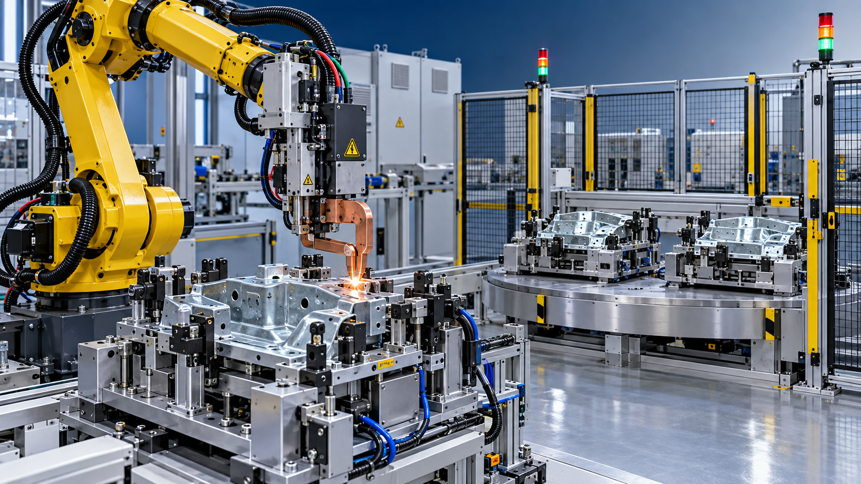
A spot welding robot can replace manual resistance welding when the joint pattern, part presentation, and production rhythm are stable enough for automation to repeat the same weld schedule without frequent human correction. The strongest case is not simply a high labor cost. It is a process in which weld quality varies between shifts, electrode condition is difficult to control by observation alone, or output is limited by the time required to position parts and operate a hand gun.
Robotic welding is especially suitable for assemblies with repeated spot locations, predictable part geometry, and sufficient volume to keep the cell utilized. Sheet-metal enclosures, brackets, cabinets, vehicle subassemblies, wire products, appliances, and fabricated frames often meet these conditions. A robot does not compensate automatically for poor fit-up, contaminated surfaces, or changing material thickness; it repeats the programmed motion and force. Replacement is therefore justified when the upstream process can present parts consistently, not merely when a manual station appears slow.
Start with process stability rather than robot speed
Manual resistance welding contains many small adjustments that may be invisible in a cycle-time study. An experienced welder can alter gun angle, squeeze timing, contact position, or applied pressure when a flange is slightly distorted. Those interventions can maintain production in a variable process, but they also conceal the real source of variation. A robot will expose that variation quickly through missed contact, expulsion, shallow nuggets, shifted welds, or excessive electrode wear.
Before selecting a robotic cell, examine a representative run of parts rather than a single approved sample. Compare hole position, flange height, nesting location, gap at the weld interface, coating condition, and surface cleanliness. If these factors remain within a controlled range, robot programming becomes straightforward. If incoming parts move noticeably in the fixture or require frequent manual alignment, the investment may need to include better locating pins, clamps, gauging, or upstream forming control.
The useful question is: can each part be located in the same position relative to the weld gun? A robot has repeatable motion, but repeatable motion does not create repeatable part location. Fixtures, datum surfaces, clamp sequence, and loading method are often more important to final weld consistency than the robot model.
Conditions that favor replacement
A robot cell gains ground when the manual process includes repeated non-welding movement. Walking a gun between spots, repositioning a heavy cable, turning an assembly, waiting for a second component, or checking alignment can consume more time than the electrical weld itself. A robot can follow a defined path while a fixture holds the workpiece, and a turntable or dual-station arrangement can allow loading on one side while welding occurs on the other. The benefit comes from reducing handling interruption, not from assuming every weld pulse becomes dramatically faster.
High electrode force is another practical trigger. Large portable guns and transformer-integrated guns can be tiring to hold and difficult to keep square to the work surface. Where weld access demands consistent force, controlled throat depth, or a fixed approach angle, a robot-mounted gun removes a major source of operator-to-operator variation. This is particularly relevant when spot locations lie along long seams, inside formed channels, or around assemblies that must be rotated manually.
Replacement also becomes compelling when quality records show recurring symptoms that are tied to execution rather than to material defects. These include uneven indentation, weld centers drifting from the intended overlap, inconsistent peel-test results, and electrode faces dressed at irregular intervals. A robotic controller can apply defined squeeze, weld, hold, and tip-dressing sequences. It also makes it easier to preserve the same welding program after a shift change or a new operator assignment.
Safety conditions matter, but they should be assessed in detail. Repetitive handling of heavy welding guns, close exposure to pinch points, sharp sheet edges, and awkward access around fixtures are credible reasons to automate. The cell still needs guarding, interlocks, safe access for tip changes, and a practical fault-recovery routine. Moving the welding gun behind a fence without resolving poor loading ergonomics merely shifts the problem to another task.
Volume alone is an incomplete investment signal
High volume supports automation, yet volume by itself can mislead. A large annual quantity made across many short batches, with frequent engineering changes and changing weld patterns, may not keep a dedicated cell productive. Conversely, a modest but steady family of similar assemblies may justify a flexible cell if one fixture base, common gun access, and reusable programs cover several variants.
Part mix should be reviewed alongside changeover effort. A robot is a good replacement candidate when variants share reference surfaces and weld access, even when their dimensions differ. It becomes less attractive when each version needs a new fixture, a different gun orientation, extensive reach adjustment, or lengthy validation before release. The practical dividing line is not the number of part numbers; it is whether each part number behaves as part of a controlled family.
Confirm that the weld is suitable for automation
Resistance spot welding depends on the interaction of current, force, time, electrode geometry, material condition, and sheet stack. A robot can control the movement and sequence, while the welding controller manages the electrical schedule. Neither component eliminates the need to establish a sound weld window. The required nugget formation must tolerate normal variation in material thickness, coating weight, and fit-up without causing expulsion or insufficient fusion.
Galvanized steel illustrates why a nominal material description is not enough. Coating affects electrical contact and electrode pickup. The process may need revised current, force, timing, cooling, and dressing intervals compared with bare steel. High-strength steels add another layer of concern because the heat-affected area and sheet combination can influence joint performance. Aluminum introduces different conductivity and surface-oxide behavior, often requiring equipment and process development that should not be assumed from a steel welding setup.
Stack-up geometry deserves equal attention. Two clean sheets with broad overlap are far easier to automate than a three-layer joint containing a gap, adhesive, weld-through primer, or formed edge close to the weld point. Adhesive may be compatible with a planned process, but it changes squeeze behavior and can affect current flow. A robotic program that performs well on dry test pieces can become unstable when production parts include sealant, oil, scale, or inconsistent coatings.
Surface preparation sometimes determines whether automation is viable. Structural steel parts produced by cutting, forming, or heat treatment can carry rust, oxide scale, and contaminants that interfere with reliable electrical contact. When surface condition is the limiting factor, a controlled cleaning stage such as a roller-type Shot blasting machine may be relevant before fabrication, provided the resulting surface profile, handling interval, and corrosion protection remain compatible with the welding sequence. Cleaning alone does not solve poor joint fit-up, and an aggressively treated surface is not a substitute for validated welding parameters.
The equipment scope is larger than the robot arm
A replacement decision should include the complete cell: robot, welding gun, transformer or medium-frequency inverter system, controller, dress station, fixture, clamps, part-present sensing, guarding, fume extraction where needed, and electrical and cooling infrastructure. Omitting any of these from the initial scope creates a misleading comparison with a manual station.
Gun selection follows access and force requirements. A C-gun can suit open flanges and relatively direct access. An X-gun can reach locations where the arms must approach from different directions. Gun mass affects robot payload, acceleration, cable management, and reach. The most compact gun is not always the right choice if it cannot maintain a square electrode approach or reach all spots without singular positions and awkward wrist angles.
Fixture design requires an early review with the intended welding path. Clamps must secure the actual weld stack, not merely hold the part generally in place. A clamp placed too close to the weld can restrict gun access; one placed too far away can allow a gap to open under electrode force. Locating a component through burr-prone edges or flexible formed features can create part-to-part movement even when the fixture appears robust. Pilot holes, machined datums, and positive stops provide more reliable references than visual alignment.
Utilities need realistic capacity planning. Resistance welding generates heat in the workpiece and electrodes, so cooling-water flow and temperature stability affect tip life and weld repeatability. Electrical demand should be considered with the transformer, welding schedule, other plant loads, and local supply characteristics. A robot cell that is mechanically installed but limited by inadequate cooling or electrical infrastructure will not reach the intended operating rhythm.
Cycle time must include the work around welding
Comparing only arc-on or weld-on time leads to poor estimates. Measure manual loading, locating, clamping, gun movement, welding, repositioning, visual inspection, tip changes, rework, unloading, and part transfer. Then map the robotic sequence with the same boundaries. A robot may reduce welding travel while adding fixture load time, safety-door delay, or programmed tool changes. Dual fixtures, automatic clamps, and sensible part presentation can reduce those losses, but they must be designed into the cell.
Downtime deserves the same treatment. Electrode dressing, replacement, cooling checks, fixture cleaning, program recovery, and weld-quality verification need assigned procedures. An automated station often produces a more visible and traceable maintenance pattern than a manual one, yet it still requires discipline. If a worn electrode cap remains in service, the robot will reproduce the same deteriorating contact condition at every programmed point.
A useful evaluation separates planned cycle time from recoverable interruption. A short robot cycle is valuable only if loading, material flow, and downstream handling can keep pace. If finished assemblies accumulate because inspection or transport cannot accept them, the robot becomes an expensive waiting point rather than a production improvement.
Use validation to distinguish a good demonstration from a dependable process
Acceptance should involve production-representative material, normal surface condition, realistic part tolerance, and the planned fixture. Demonstrations using flat coupons or perfectly prepared samples are appropriate for initial feasibility, but they cannot confirm full assembly behavior. Weld location, indentation, nugget consistency, expulsion, electrode wear progression, and access to every programmed point should be evaluated through a meaningful production sequence.
Program design also needs a response to normal variation. Part-present sensors can prevent a cycle from running on an empty fixture. Clamp confirmation can prevent welding before the stack is seated. Weld monitoring can identify deviations in current, voltage, force, or displacement, but alarm limits must be based on proven process behavior. Limits set too narrowly create frequent stops; limits set too broadly produce records without useful protection.
Do not treat a robot as a remedy for unstable upstream cutting, stamping, bending, or forming. When the robot repeatedly encounters the same offset, the correct action may be to correct the fixture datum or upstream feature rather than adding program offsets. Offsets can mask a one-time issue, but they become fragile when material lots or tooling conditions change.
When manual resistance welding remains the better fit
Manual welding remains appropriate for prototypes, repair work, low-frequency custom assemblies, and jobs where each part requires judgment-based fitting. It also has value during early product development, when weld positions and part geometry are still changing. A flexible manual station can absorb variation while the design and manufacturing process mature.
The transition point arrives when that flexibility turns into recurring adjustment, inconsistent quality, difficult gun handling, or a throughput constraint. At that stage, the proper project is not simply “add a robot.” It is to establish stable parts, controlled locating, validated weld schedules, and a cell layout that keeps the robot supplied. When those conditions are present, robotic spot welding becomes a repeatable production process rather than a costly automated version of an unstable manual operation.
search
Products Navigation
Send Us A Message