




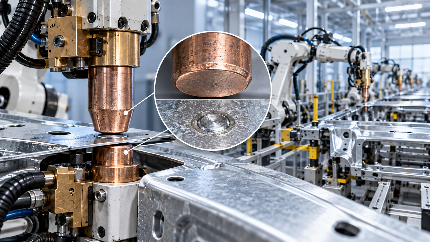
How Electrode Wear Affects Robotic Spot Welding Quality
In robotic spot welding, electrode wear is a critical factor that can quietly compromise weld strength, consistency, and production safety.
For quality control and safety managers, understanding worn-electrode effects on current flow, nugget formation, and defect rates is essential for reliable operations.
The overall judgement is straightforward: electrode wear is manageable, but only when it is measured, controlled, and linked to weld-quality evidence.
Why Electrode Wear Matters in Robotic Spot Welding
Robotic spot welding depends on repeated, controlled contact between electrode tips and sheet material. As tips wear, that contact condition changes gradually.
Because robots repeat programmed motion accurately, operators may assume weld quality remains stable. However, a robot can repeatedly create the same poor weld.
Electrode wear changes the effective contact area, electrical resistance, heat balance, force distribution, and surface condition at the weld location.
These changes can reduce weld quality long before visible defects appear. This makes electrode condition a process-control issue, not merely a maintenance concern.
For quality teams, the most important point is that worn electrodes often create variation rather than immediate total failure.
Some welds may still pass visual inspection while having reduced nugget size, lower peel strength, or inconsistent performance during crash loading.
Safety managers should also consider indirect consequences. Weak or inconsistent welds can create structural risks, rework exposure, handling hazards, and production interruptions.
In high-volume manufacturing, minor deterioration across thousands of welds can become a major quality-cost problem before anyone identifies its root cause.
How Wear Changes Current Flow and Heat Generation
A new electrode tip has a defined profile and contact diameter. This geometry concentrates current and force in a predictable welding area.
During production, repeated heating, pressure, material pickup, and mechanical impact flatten or enlarge the electrode face.
As the contact area grows, current density decreases. The welding current is distributed across a larger surface instead of concentrating at the intended point.
Lower current density can reduce heat generation at the faying interface, where the sheets must form a strong weld nugget.
When heat is insufficient, the nugget may be smaller than required, poorly fused, or absent in localized areas.
At the same time, worn tips may develop uneven contact surfaces. One side can carry more current and force than another.
This uneven distribution creates asymmetric heating. The resulting weld may contain an off-center nugget, inconsistent indentation, or unpredictable expulsion behavior.
Material coatings make the issue more complex. Zinc-coated steel can transfer coating material onto copper alloy electrodes during repeated cycles.
That pickup increases contact resistance and changes thermal behavior. A welding schedule that worked earlier may become unstable without any program modification.
Quality personnel should avoid assuming that a higher resistance reading always means a stronger weld. Resistance must be interpreted with process context.
Excessive resistance near the electrode surface can generate heat in the wrong location, promoting electrode sticking, surface damage, or expulsion.
Reliable robotic spot welding requires heat to develop primarily between the sheets, rather than excessively at the electrode-to-sheet interface.
What Happens to Nugget Formation and Weld Strength
The weld nugget is the fused region joining the metal sheets. Its size, location, continuity, and metallurgical condition determine functional weld strength.
Electrode wear commonly reduces the force and current concentration needed to form a consistent nugget across every programmed weld point.
As tip diameter increases, the same welding current may no longer provide enough energy density to achieve the validated nugget diameter.
Production teams sometimes respond by increasing current. This can temporarily restore weld strength, but it does not correct the underlying electrode condition.
Higher current may increase spatter, electrode sticking, indentation depth, coating damage, and cable or transformer loading.
It can also narrow the acceptable process window. Small changes in sheet thickness, coating condition, or fit-up then produce larger quality variation.
Worn electrodes can create both undersized and overheated welds. The outcome depends on the wear pattern, contamination level, material stack, and programmed force.
For example, a broad polished tip may produce insufficient fusion, while a contaminated or pitted tip may create localized overheating and expulsion.
Peel tests, chisel tests, and destructive cross-sections remain useful because they reveal whether actual nugget formation matches the approved process expectation.
However, destructive testing alone is reactive when sample frequency is low. Managers need electrode monitoring that identifies deterioration before defective parts accumulate.
Warning Signs Quality Teams Should Not Ignore
The earliest warning sign is often a gradual drift in weld-monitoring data rather than a visibly damaged electrode.
Changes in dynamic resistance, weld current, electrode displacement, force feedback, or weld time can indicate changing contact conditions.
A rising rate of expulsion, sparks, sticking, or surface marking deserves immediate investigation, especially when equipment settings have not changed.
Visible electrode symptoms include flattened tips, mushrooming, pitting, cracking, coating pickup, discoloration, and inconsistent tip-face geometry.
Quality inspectors should compare actual tip diameter with the approved dressing limit. Visual judgement alone is not sufficiently repeatable for critical production.
Inconsistent indentation patterns on finished assemblies can also signal uneven electrode contact or excessive electrode-face wear.
Another warning sign is increasing schedule compensation. If operators repeatedly raise current or welding time to maintain test results, electrode control may be failing.
Unplanned tip dressing, frequent weld-gun maintenance, and unstable weld-monitor alarms are operational signals that should be reviewed together.
Safety managers should track these signals because repeated corrective interventions increase exposure to hot surfaces, pinch points, electrical isolation tasks, and unplanned access.
Trend data is more valuable than isolated readings. A single outlier may reflect a material issue, but a sustained trend usually indicates process deterioration.
How to Separate Electrode Wear from Other Welding Problems
Electrode wear is common, but it is not the only cause of poor robotic spot welding quality. Effective investigation must avoid premature conclusions.
Material thickness variation, coating changes, oil contamination, poor fit-up, gun misalignment, inadequate force, and cooling failure can produce similar symptoms.
Begin by checking the electrode face, tip diameter, dressing history, and number of welds completed since the last verified maintenance event.
Next, confirm the actual welding current, weld force, squeeze time, hold time, and cooling-water flow against the approved welding schedule.
Inspect the robot path and gun alignment when wear appears uneven. A consistently angled approach can accelerate one-sided electrode degradation.
Check sheet stack condition and fixture repeatability. Gaps between sheets can change resistance and demand more energy than the validated process allows.
Cooling problems deserve special attention. Insufficient water flow or elevated water temperature can soften electrode material and accelerate tip deformation.
A structured fault tree helps teams distinguish normal consumable wear from a deeper mechanical or process-control failure.
The investigation should document evidence, corrective action, verification results, and responsibility. This supports traceability during customer audits and internal reviews.
Quality managers should require proof that corrective action restores the approved weld window, rather than accepting a temporary improvement in appearance.
Setting Practical Tip-Dressing and Replacement Controls
Tip dressing restores electrode geometry by removing contamination and reshaping the contact face. It is one of the most effective controls for repeatable welding.
Its interval should be based on weld count, material type, coating, tip material, observed wear rate, and validated test results.
A fixed interval may be suitable for stable production, but high-strength steel, galvanized materials, or changing stacks may require adaptive controls.
Do not choose a dressing interval solely because it reduces downtime. Overextending electrode life can create expensive downstream quality failures.
Conversely, dressing too frequently wastes electrode material, increases cycle interruptions, and may introduce geometry variation if dresser performance is inconsistent.
Each dressing operation should be verified for tip profile and diameter. A poorly maintained tip dresser can repeat the same defect across every electrode.
Replacement criteria should include minimum electrode length, repeated pitting, cracks, cooling-channel concerns, unacceptable alignment, and inability to maintain the approved tip geometry.
Recording electrode life by gun, product family, shift, and material lot can reveal patterns that average maintenance records conceal.
For critical joints, connect the dressing counter to the robot or weld controller so the process cannot continue beyond the validated limit.
This interlock approach reduces dependence on manual memory and provides a clearer audit trail for quality assurance.
Using Data to Control Wear Before Defects Escape
Modern robotic spot welding cells can provide useful process data, but data only creates value when teams define action limits and response rules.
Monitor weld current, voltage, dynamic resistance, electrode force, displacement, cycle count, cooling conditions, and alarm frequency where available.
Establish a baseline using confirmed good welds made with properly dressed electrodes and representative production materials.
Then define normal operating bands, warning thresholds, and stop limits. These values should reflect validated weld performance, not arbitrary machine capability.
Statistical process control can identify gradual drift before destructive tests fail. Trend charts are especially useful for multi-shift and high-volume operations.
Quality teams should correlate monitoring data with peel-test results, macroetch inspections, and customer-relevant performance tests whenever possible.
This correlation prevents false confidence in a single sensor signal. A stable current value does not guarantee correct electrode force or nugget formation.
Review data by individual welding gun. Shared averages can conceal a deteriorating gun within a production line containing otherwise stable equipment.
Clear escalation rules are essential. Operators need to know when to dress tips, call maintenance, quarantine parts, or stop the cell.
Safety procedures should define lockout requirements before manual inspection, dressing maintenance, or electrode replacement within the robotic welding area.
Reducing Safety and Business Risks from Electrode Failures
Electrode wear affects more than weld acceptance. It can increase operational risk through expulsion, unexpected sticking, rework, and frequent manual intervention.
Expulsion can eject hot particles and damage adjacent components. It also increases the risk of burns, fire exposure, and contamination of fixtures.
Repeated rework creates additional handling and welding cycles, which may expose workers to awkward access positions and unplanned production pressure.
For safety managers, electrode maintenance should be included in formal risk assessments for robotic cell operation and preventive maintenance activities.
Controls should cover energy isolation, access permission, hot-work awareness, protective equipment, tool condition, and safe verification after restarting the cell.
From a business perspective, poor electrode control raises scrap, repair labor, inspection costs, customer claims, and line stoppages.
It may also reduce confidence in automated welding investment. The real issue is usually not automation itself, but inadequate consumable and process governance.
Well-controlled electrodes improve first-pass yield, stabilize cycle time, reduce emergency maintenance, and support more predictable delivery performance.
These benefits make electrode management a measurable quality investment rather than a low-level consumable expense.
Supporting Consistent Welding Beyond the Spot-Welding Cell
Manufacturers often manage multiple welding processes, including robotic spot welding, seam welding, pipe fabrication, and pressure-vessel production.
Across these processes, stable workpiece positioning remains important because movement, poor access, and inconsistent joint orientation can affect quality and operator safety.
For cylindrical components, a Self aligning welding rotator can support stable rotation during circumferential and longitudinal seam welding.
Available for loads from 5 to 200 tonnes, this equipment supports pipes, tanks, boilers, and pressure vessels while reducing manual turning requirements.
Its VFD-controlled rotation and remote hand control can help position a weld joint at a consistent working angle for continuous welding operations.
Although it serves a different welding application, the same quality principle applies: repeatable positioning helps maintain stable process conditions and reduces avoidable variation.
Quality managers should evaluate welding equipment as an integrated system, including consumables, fixtures, workpiece support, programming, maintenance, and inspection feedback.
What an Effective Electrode-Control Program Looks Like
An effective program begins with documented electrode specifications, approved tip geometry, material compatibility, dressing methods, and replacement criteria for each weld application.
It also assigns clear ownership. Production monitors daily conditions, maintenance maintains guns and dressers, and quality verifies performance against acceptance requirements.
Training should explain why operators must report early symptoms. Personnel are more likely to act consistently when they understand the quality consequences.
Audit records should include weld counts, dressing events, tip measurements, process trends, destructive-test results, repairs, and nonconformance decisions.
Review these records regularly with production and engineering. Repeated wear-related problems may justify changes to tip material, cooling, force settings, or welding schedules.
When introducing a new material, coating, or vehicle component, revalidate electrode life rather than relying on historical intervals from another product.
Change management is particularly important for advanced high-strength steels, mixed-material stacks, and coated components with narrow welding process windows.
The strongest programs combine preventive maintenance with real weld-quality verification. Neither approach alone provides adequate protection against escaped defects.
Conclusion: Treat Electrode Wear as a Controlled Quality Variable
Electrode wear directly affects current density, heat distribution, nugget formation, weld strength, surface appearance, and process stability in robotic spot welding.
For quality control and safety managers, the key decision is not whether electrodes will wear. They will, under every normal production condition.
The practical objective is to detect wear early, dress or replace electrodes at validated limits, and verify that weld quality remains within specification.
Use measurable tip geometry, weld-monitor trends, destructive verification, maintenance records, and clear escalation rules to control the risk before parts escape.
When electrode management is integrated into daily process control, robotic spot welding becomes more consistent, safer to operate, and less vulnerable to costly hidden defects.