




When does welding robot for long seam welding require laser seam tracking versus vision-based guidance?
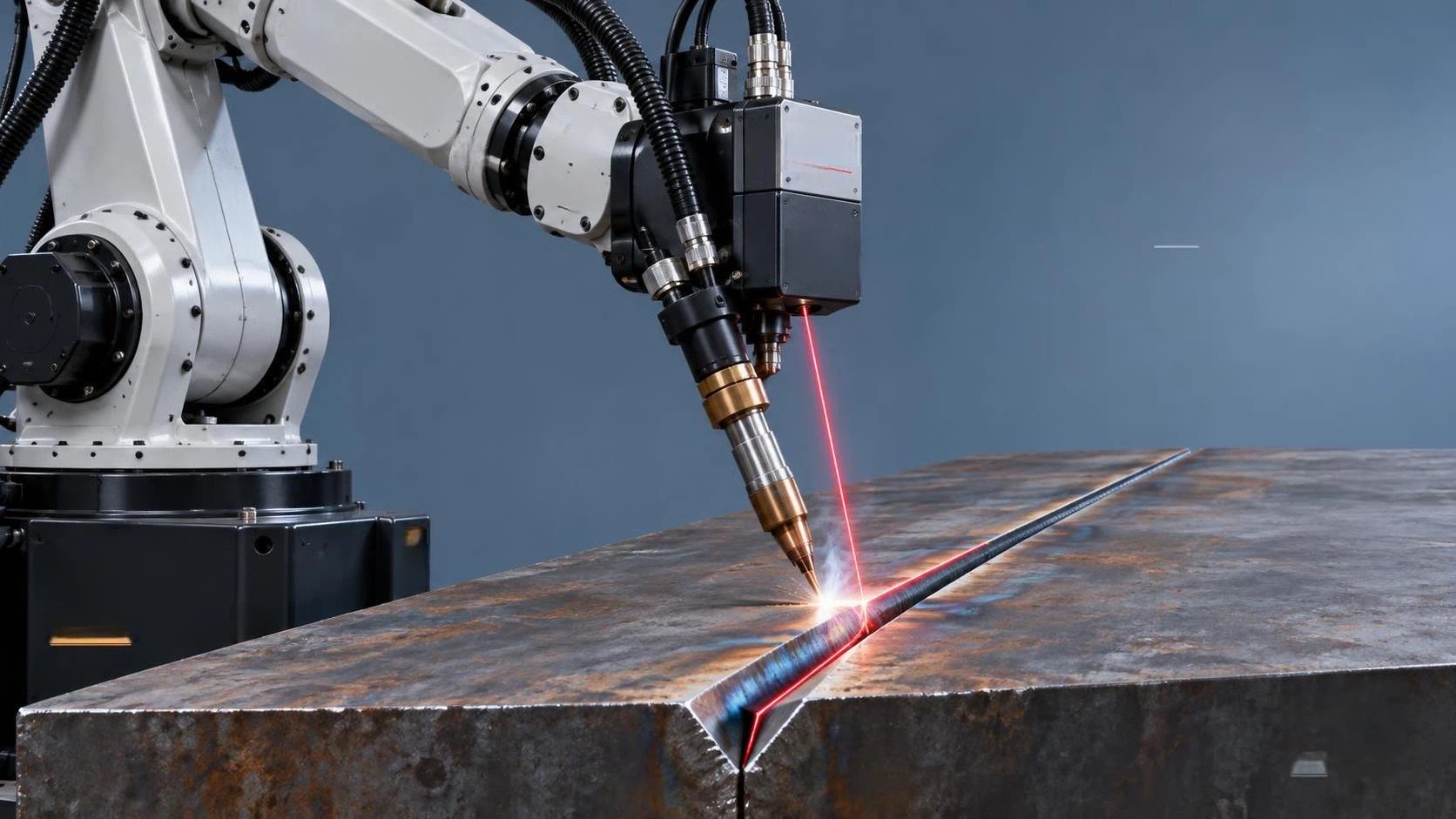
When does a welding robot for long seam welding actually need laser seam tracking instead of vision-based guidance?
For technical evaluators specifying robotic systems for long seam welding—especially in structural steel, pressure vessel, shipbuilding, or heavy equipment fabrication—the choice between laser seam tracking and vision-based guidance isn’t about “which is newer” or “which has more pixels.” It’s about whether the system can maintain weld quality *within your joint tolerance envelope*, under *your production conditions*, without introducing hidden integration overhead or runtime instability.
Laser seam tracking wins when three conditions converge: (1) joint geometry varies beyond ±0.3 mm in root gap or mismatch; (2) ambient lighting or surface reflectivity disrupts consistent contrast detection; and (3) real-time correction latency must stay below 15 ms to avoid arc deflection or porosity on high-speed passes. Vision-based guidance can suffice—but only if all three conditions are tightly controlled. Misjudging this threshold leads not to minor rework, but to systematic weld rejection in QA audits or costly post-weld grinding that undermines ROI.
Joint tolerance is the decisive factor—not material or seam length
Many assume “long seam” automatically implies laser tracking. That’s misleading. A 12-meter seam in precisely machined H-beam flanges with ±0.15 mm fit-up tolerances runs reliably with calibrated stereo vision—even at 800 mm/min. But a 1.2-meter seam in rolled pipe spools with variable mill-scale thickness, inconsistent bevel angles, and thermal distortion during multi-pass welding? That same vision system often fails mid-pass, triggering manual intervention or scrap.
The critical metric isn’t seam length—it’s local joint repeatability. Laser triangulation measures actual groove geometry point-by-point, independent of surface finish or contrast. Vision relies on edge detection algorithms trained on idealized profiles. When mill scale, rust, or inconsistent torch shielding gas creates localized glare or shadowing, vision systems misread groove width by 0.4–0.7 mm—a margin that exceeds typical GMAW tolerance for full-penetration welds. Laser sensors, by contrast, return stable Z-axis data even on oxidized carbon steel or aluminum alloys with high reflectivity.
Ambient conditions matter more than you test in the lab
Factory lighting is rarely uniform. Overhead LED banks create specular reflections on hot metal surfaces. Nearby grinding or plasma cutting introduces airborne particulates that scatter camera light paths. Even dust accumulation on lens covers degrades vision accuracy faster than laser sensor windows—because vision requires high-contrast image segmentation, while laser triangulation depends only on reflected spot position.
We’ve seen vision-guided robots perform flawlessly in climate-controlled prototype cells—then fail repeatedly on the shop floor where crane-mounted lights swing across workpieces, or where HVAC drafts cool weld pools unevenly, altering surface emissivity. Laser tracking, though sensitive to heavy smoke or spatter buildup on the sensor window, recovers instantly after a brief air blast. Its signal-to-noise ratio remains robust under variable illumination because it operates in its own narrow-band wavelength—not competing with ambient light.
Real-time correction speed separates functional from compliant
Welding standards like ISO 15614-1 or ASME Section IX don’t specify tracking method—but they do require consistent fusion, lack of undercut, and dimensional compliance across the entire seam. That demands sub-20 ms closed-loop response. Vision systems with onboard GPU processing now achieve ~25 ms latency end-to-end (image capture → processing → trajectory update). Laser tracking systems—particularly those using FPGA-accelerated triangulation—routinely deliver 8–12 ms.
This difference becomes critical on thick-section, multi-pass welds where interpass temperature control and bead placement dictate mechanical properties. A 10-ms delay means the robot corrects for a joint deviation that occurred 2.5 mm earlier—potentially causing overlap or lack-of-fusion at the toe. In practice, this shows up as increased NDT rejection rates in radiographic testing, not visible defects on the surface.
Integration complexity isn’t just about wiring—it’s about validation scope
Laser tracking adds hardware (sensor head, mounting bracket, air purge), but simplifies software integration: most OEM robot controllers accept analog or EtherCAT position offsets directly. Vision guidance often requires separate industrial PCs, custom calibration routines per fixture, and ongoing recalibration when tooling shifts—even microscopically. That recalibration isn’t a one-time setup task; it’s a recurring QA checkpoint that extends changeover time and introduces human error.
Where laser systems integrate cleanly into existing PLC logic and safety chains, vision solutions frequently sit outside the robot’s motion control loop—relying on external motion planners that introduce jitter or timing drift. This isn’t theoretical: field deployments show vision-guided systems require 15–20% more operator oversight per shift to verify tracking stability, especially after maintenance cycles or seasonal humidity changes.
When vision still makes sense—and where hybrid approaches emerge
Vision guidance remains viable for applications where joint consistency is engineered—not assumed. Examples include precision-machined components for railcar underframes or wind tower sections with CNC-cut edges and pre-assembled jigs. Here, vision’s ability to detect part presence, verify orientation, and flag gross misalignment before arc start adds value beyond seam tracking alone.
Hybrid use cases are gaining traction too—not as marketing buzzwords, but as pragmatic compromises. One customer welding large-diameter transmission shafts uses vision for initial seam search and coarse alignment, then switches to laser tracking for final pass execution. Another fabricator of modular power substations deploys vision for seam finding on painted assemblies (where laser reflection is unreliable), then transitions to laser once the torch cleans the surface.
These aren’t “best-of-both-worlds” solutions—they’re risk-mitigation strategies. They acknowledge that no single sensing modality eliminates all uncertainty. The engineering discipline lies in matching the sensing method to the dominant source of variation in *your* process—not the vendor’s brochure.
One practical implication for upstream processes
If your long seam welding application involves parts that feed into subsequent cold-forming operations—like threaded fasteners for structural connections—joint consistency gains new weight. A Z28-250 thread rolling machine produces GB197 Grade 2 threads with Ry 0.1–0.8 μm surface finish, but only if incoming blanks have precise diameter and straightness. Similarly, robotic welding quality depends less on the tracker’s specs than on how well upstream cutting, bending, and fit-up hold dimensional control. Investing in laser tracking won’t compensate for inconsistent bevel angles from a worn plasma torch—or for thermal distortion caused by unbalanced clamping.
So before selecting tracking technology, audit your joint preparation process first. Measure actual gap and mismatch distributions across 50 representative seams—not just best-case samples. If >30% exceed ±0.3 mm, laser tracking isn’t optional—it’s the baseline requirement for first-pass yield. If variation stays within ±0.15 mm, invest in vision system validation—not hardware upgrades.
There is no universal answer. But there is a reliable decision filter: define your worst-case joint condition, simulate its impact on weld geometry under your travel speed and heat input, and test the tracking method against that condition—not against ideal lab conditions. That’s where technical evaluation moves from specification to assurance.
search
Products Navigation
Send Us A Message