




Wire Feed Welding Equipment: How to Choose the Right Wire Feeder for Mild Steel vs. Aluminum MIG Applications
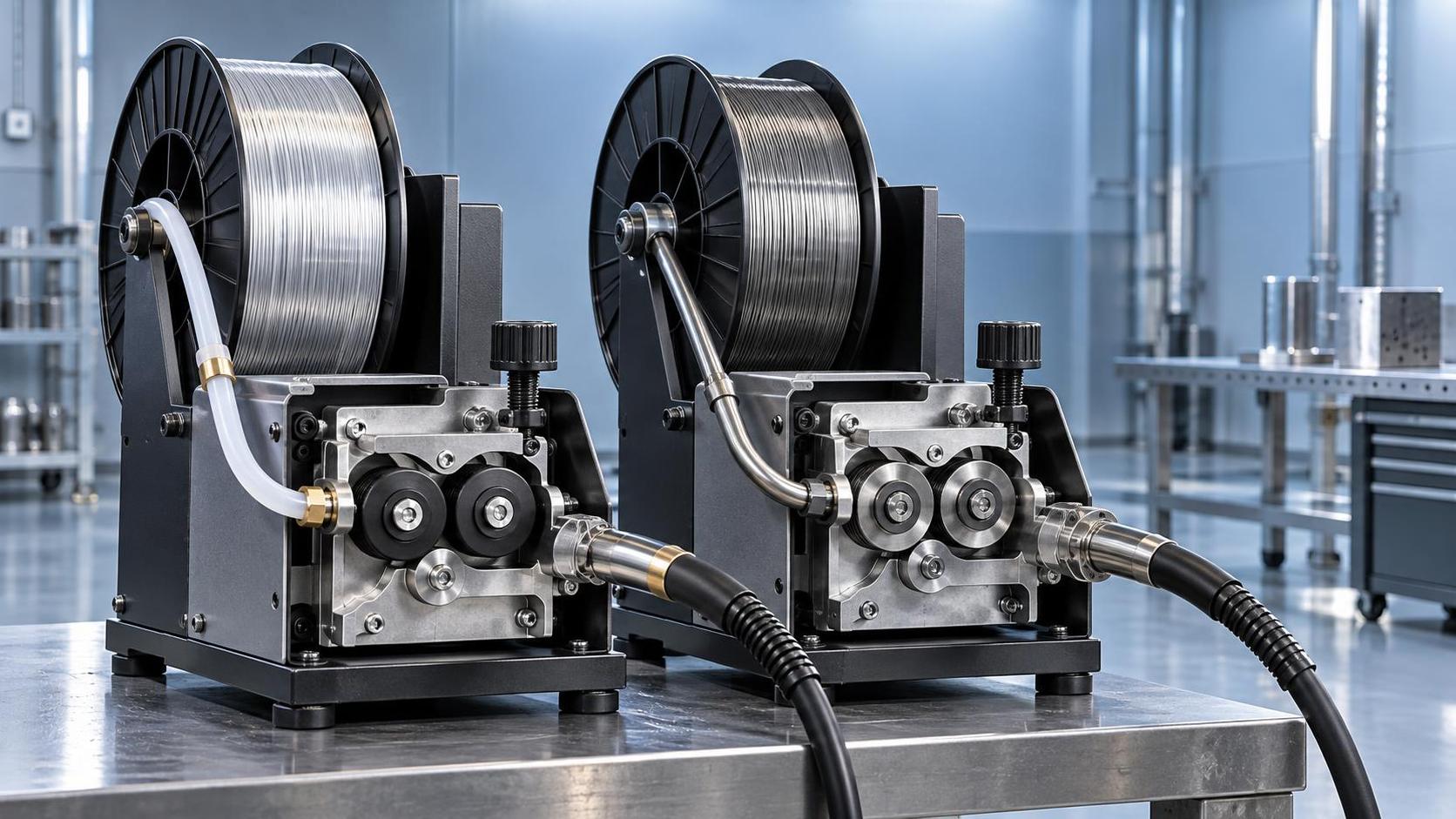
Why “One Feeder Fits All” Is a Costly Myth in MIG Welding
If you’re evaluating wire feeders for both mild steel and aluminum MIG applications—and especially if your shop runs mixed-material batches—you’ve likely encountered vendors offering “universal” or “dual-material” feeders. That sounds efficient. In practice, it often means compromised arc starts, inconsistent wire feeding, increased downtime from liner clogging or drive roll slippage, and welds that pass visual inspection but fail tensile or bend testing under production load. The core issue isn’t compatibility on paper; it’s how material-specific physics—thermal conductivity, oxide layer behavior, and mechanical wire properties—translate into real-world feeder performance.
The Two Material Realities You Can’t Ignore
Mild steel and aluminum demand fundamentally different handling at the wire feed stage—not just different parameters, but different mechanical responses:
- Mild steel (ER70S-6, 0.035"–0.045") is stiff, forgiving, and tolerant of moderate backpressure. It feeds reliably through standard U-groove drive rolls with steel liners—even over longer push-pull distances—as long as tension is set conservatively and liner routing avoids sharp bends.
- Aluminum (ER4043/5356, 0.030"–0.047") is soft, springy, and highly sensitive to friction. Its oxide layer increases surface drag, while its low yield strength means even slight misalignment or excessive drive roll pressure causes deformation, shaving, or “birdnesting.” Aluminum also requires shorter, smoother liner paths (ideally <10 ft), non-metallic liners (PTFE or nylon), and specialized drive rolls—typically V-groove or U-groove with rubber or Delrin inserts—to grip without crushing.
This isn’t about preference—it’s about force transmission. A feeder optimized for steel applies too much pinch force and rotational torque for aluminum wire, leading to inconsistent feed speed and erratic arc behavior. Conversely, a feeder tuned for aluminum lacks the torque reserve needed for thicker steel wires or cold starts after spool change.
What Actually Matters in Feeder Selection—Not What Brochures Highlight
Technical evaluators should prioritize four functional criteria—not marketing categories:
1. Drive Roll Geometry & Material Compatibility
U-groove steel rolls work for steel—but they’ll gouge or flatten aluminum wire. V-groove rolls with soft inserts provide conformal contact, reducing deformation. Crucially, the roll must be easily swappable *without recalibrating motor feedback*. Some feeders require firmware resets or torque recalibration when switching roll types; avoid those. Look for mechanical indexing systems where roll position is physically repeatable within ±0.1 mm.
2. Liner System Design
A “compatible liner” isn’t enough. For aluminum, the liner must be fully sealed at both ends (no exposed metal transitions), have minimal internal diameter variation (<±0.002"), and use low-friction coatings. Steel liners—even “aluminum-rated” ones—often have micro-burrs from manufacturing that catch soft wire. PTFE-lined conduits with smooth, continuous inner surfaces reduce resistance by up to 40% compared to standard steel liners, directly improving start reliability and voltage stability.
3. Motor Response & Feedback Loop Speed
Aluminum’s lower thermal mass means arc voltage fluctuates faster during short-circuit transfer. A feeder with slow current-loop response (>20 ms) can’t compensate quickly enough, causing burnback or porosity at the start of each weld. Verify the motor controller’s sampling rate: ≥1 kHz is baseline; ≥2 kHz is recommended for pulse-MIG aluminum applications. Also check whether the feeder uses closed-loop current sensing (not just voltage-based estimation)—this affects repeatability across spool diameters.
4. Spool Handling & Tension Management
Aluminum spools are typically 10–15 lb (vs. 33–50 lb for steel). Lighter spools mean lower inertia, so feeder brake systems must modulate tension dynamically—not just apply fixed spring pressure. Over-braking causes wire stretch and feed hesitation; under-braking leads to backlash and tangles. Look for feeders with active brake control tied to motor torque feedback—not passive mechanical brakes.
When Integrated Automation Changes the Equation
In semi-automated cells, feeder choice remains largely a standalone decision. But in robotic MIG lines—especially those handling mixed materials—the feeder becomes part of a tightly coupled control loop. Voltage drop across long cable runs, robot motion-induced wire whip, and program-triggered parameter shifts all stress feeder responsiveness. Here, consistency matters more than raw speed.
Take the Multipurpose Handing Robot BR20iB-20, for example: its ±0.08 mm repeatability enables precise torch positioning, but only if wire feed velocity matches programmed travel speed within ±1.5%. A feeder with slow acceleration ramp-up or inconsistent start delay will undermine that precision—regardless of robot accuracy. In such setups, feeders with integrated CANopen or EtherNet/IP interfaces (not just analog 0–10 V) allow real-time synchronization with robot motion controllers, reducing latency between path command and wire delivery.
Practical Evaluation Checklist Before Procurement
Don’t rely on spec sheets alone. Test under conditions matching your actual workflow:
- Run 3 consecutive 10-minute welds on 1/4" aluminum plate using 0.035" ER4043—check for consistent arc starts, absence of stubbing, and post-weld wire tip condition (no mushrooming or flattening).
- Switch to 0.045" ER70S-6 on 3/8" steel, same joint prep. Monitor for feed hesitation during rapid direction changes (e.g., weaving patterns) and measure voltage variance across a 5-second segment.
- Change spools mid-shift—time how long it takes to re-establish stable feeding at full amperage. If >90 seconds, consider tension auto-calibration features.
- Verify liner replacement procedure: Can it be done in <5 minutes without disassembling the entire wire path? If not, factor in scheduled maintenance time—not just uptime.
No “Universal” Solution—But a Clear Path Forward
There is no single wire feeder that delivers equal performance on mild steel and aluminum without trade-offs. The right approach depends on your operational reality:
- High-mix, low-volume shops benefit from dedicated feeders per material—paired with quick-change mounting brackets—rather than one “flexible” unit that underperforms both.
- Robotic lines running both materials should treat the feeder as part of the robot’s peripheral ecosystem. Prioritize interface compatibility, closed-loop control, and documented response times over maximum feed speed.
- New installations should budget for separate feeder modules (e.g., push-pull for aluminum, direct-drive for steel) rather than retrofitting later—wiring, shielding, and space constraints become prohibitive once the cell is commissioned.
Ultimately, wire feed quality isn’t a consumable cost—it’s a foundational variable in weld integrity, operator efficiency, and scrap reduction. Choosing based on material physics—not catalog claims—cuts troubleshooting time, improves first-pass yield, and extends consumable life. That’s where technical evaluation pays off—not in the spec sheet, but in the weld bead.
search
Products Navigation
Send Us A Message