




Are Chinese Welding Robots Compatible With European CNC Cutting Systems?
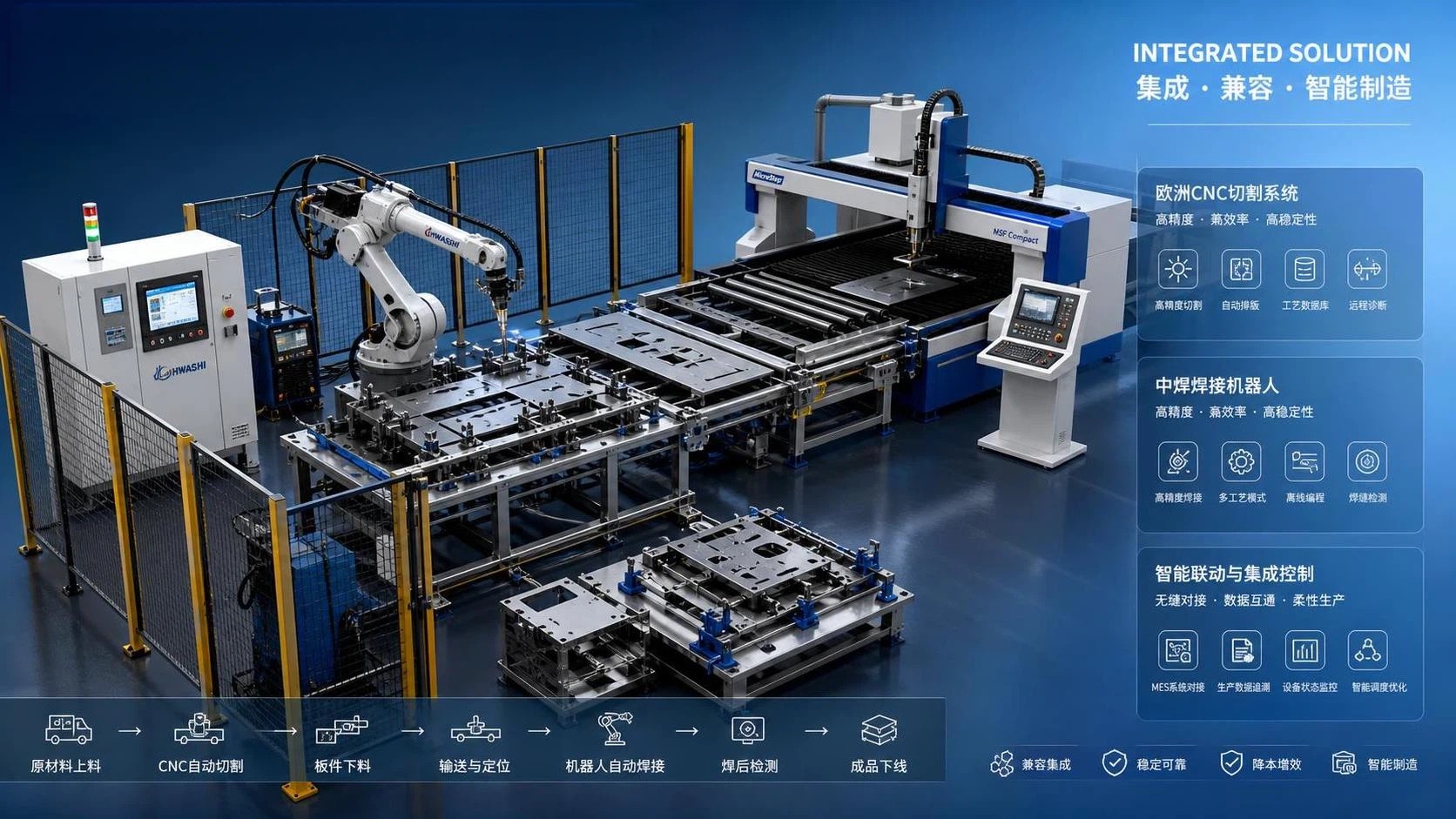
Yes, Chinese welding robots can be compatible with European CNC cutting systems, but compatibility is usually a practical engineering question rather than a simple yes-or-no label. In mixed production lines, the robot arm itself is only one part of the result. The real issue is whether the robot controller, welding power source, cutting machine controller, fixtures, positioners, safety devices, and production software can exchange the right signals at the right time without creating unstable cycle timing or unsafe motion.
How compatible are Chinese-made welding robots with European CNC cutting systems? In many installations, they can work together if the integration scope is clearly defined from the start. Basic coexistence is usually straightforward: a CNC plasma, flame, or laser cutting machine prepares parts, and a welding robot handles the next station. Full automation, where cut parts are identified, transferred, fixtured, welded, and tracked with little manual intervention, requires much closer attention to fieldbus protocol support, I/O mapping, coordinate consistency, and safety logic.
Where compatibility usually works well
At the mechanical level, compatibility is often manageable. A welding robot does not need to come from the same source as the cutting machine to weld carbon steel brackets, stainless enclosures, H-beam assemblies, box sections, or plate fabrications. If the cut part arrives within the expected dimensional tolerance, the robot can follow a taught path or a corrected path based on seam tracking. This is especially true when the welding station is separated from the cutting station by buffering, part sorting, or manual loading.
Electrical integration can also be relatively direct when the required link is limited to standard signals such as cycle start, machine ready, fault reset, door closed, fixture clamped, weld complete, and emergency stop chain status. In that kind of layout, even if the CNC cutting system and welding robot use different native controller architectures, the line may still run reliably through digital I/O, relays, safety modules, or a PLC acting as the coordination layer.
Compatibility becomes more realistic when the process is tolerant of small variation. Fillet welds on medium-thickness carbon steel, non-cosmetic structural joints, and repeated parts with stable fixturing are easier to integrate than thin stainless seams, visible surface welds, or heat-sensitive assemblies where every small mismatch in cut edge, gap, or torch angle quickly shows up in the result.
Where problems usually appear first
The first obstacle is often not the robot arm. It is communication. European CNC cutting systems may use specific industrial communication standards for machine status, recipe transfer, production queue handling, nesting feedback, or downstream automation triggers. A Chinese welding robot may support some of these interfaces, support them through optional modules, or rely mainly on hardwired I/O unless a higher-level integration package is added. If the required signal list is vague at the quotation stage, later integration becomes slower and more expensive.
Another common problem is coordinate logic. A cut part may be referenced from the cutting table origin, while the welding robot uses a different frame based on a jig, rotary positioner, or external axis zero point. If the line assumes that CAD/CAM data can move directly from cutting to welding without redefining part orientation, trouble starts quickly. Mirrored parts, bevel direction, kerf compensation, and edge numbering can all cause welding paths to be assigned to the wrong side of the part.
Thermal distortion also gets underestimated. A European CNC cutting system may produce excellent profile accuracy on plate, but if piercing sequence, feed rate, or heat input leaves residual stress in the part, the robot may receive a component that no longer matches the taught weld path after release from the cutting bed. This is especially relevant for long thin sections, asymmetric parts, and stainless steel components where warping after cutting can be more noticeable.
Protocol support matters more than country of origin
When people ask whether Chinese welding robots are compatible with European CNC cutting systems, they sometimes focus too much on geography and not enough on interface definition. A robot controller can be technically suitable if it supports the required industrial network, or if an intermediate PLC can translate the signals without introducing unstable behavior. If the system only needs machine interlocking and simple station handshaking, brand origin may matter much less than the completeness of the electrical documentation.
More advanced cells usually require clearer answers to questions such as these:
- Will the robot receive only start and stop commands, or does it need structured job data tied to part numbers, weld schedules, and fixture selection?
- Is seam tracking handled locally by the welding package, or is the line expected to pass geometry data from upstream cutting or offline programming software?
- Does the installation need safe speed, safe zones, interlocked access, and coordinated restart behavior across multiple machines?
- Are external axes involved, such as head-tail positioners, welding manipulators, traveling columns, or gantry transfer units?
If these questions are answered early, integration risk drops sharply. If they are left to the commissioning stage, the robot and CNC cutter may both be functional on their own but still awkward together.
Software compatibility is usually narrower than people expect
Mechanical equipment often gets described as “compatible” when basic signal exchange works, but software compatibility is a stricter standard. A CNC cutting system may generate nesting files, bevel paths, cut sequence records, or production identifiers. A welding robot may need job files, torch orientation data, weave parameters, touch sensing offsets, and multi-pass sequencing. Those data structures are not automatically interchangeable.
In practice, software integration often falls into one of three levels. The simplest level is independent operation: the cutting machine prepares parts, and the robot works from manually selected programs. The next level is coordinated operation: part IDs, fixture calls, and batch status are exchanged through a PLC or production control layer. The most difficult level is process-linked automation, where cut geometry influences robotic weld generation with limited manual teaching. That last level may be possible, but it depends heavily on the specific controller openness, file formats, and post-processing tools available.
A frequent misunderstanding is that CAD files alone solve the problem. They do not. Weld planning depends on joint type, groove preparation, fit-up condition, gap variation, welding position, and accessibility. A part that is easy to cut automatically is not automatically easy to weld robotically.
Cut quality affects welding compatibility directly
Compatibility between a welding robot and a CNC cutting system is also a process issue. The robot can only work consistently if the edge condition from cutting is suitable for the welding method. Plasma-cut carbon steel may carry oxide on the edge, and if that oxide is not removed where necessary, arc stability or fusion quality may suffer. Flame-cut thicker plate can have hardened areas or edge irregularity depending on the setup. Laser-cut edges are often cleaner, but reflective material, burr formation, and heat tint can still influence the next step.
For MIG or MAG robotic welding on structural steel, the line often benefits from stable edge preparation, controlled root gap, and predictable tack strategy. For TIG welding on stainless steel, the tolerance window may be narrower, and fixture quality becomes much more important. Aluminum brings its own complications, especially if oxide removal, wire feeding behavior, and thermal conductivity are not built into the process design from the beginning.
Bevel cutting deserves special attention. If the European CNC cutting system produces bevels for thick plate weld prep, the welding robot must be programmed around actual groove geometry, not nominal drawings alone. Groove angle, land, root face condition, and dross removal all affect torch access and the number of passes required. A mismatch here is often blamed on robot incompatibility when the actual issue is incomplete transfer of weld preparation data.
Safety integration cannot be treated as an afterthought
Even when motion control and welding quality look acceptable, compatibility is incomplete if the safety architecture is weak. A mixed line may include fencing, light curtains, interlocked doors, emergency stops, enabling devices, servo positioners, loaders, and conveyors. The stopping behavior of the robot cell has to be coordinated with surrounding equipment so that a fault in one station does not create a hazardous restart sequence elsewhere.
If the installation is intended for a European production environment, safety circuits, documentation, and validation generally need to align with the required local expectations for machine integration. That does not automatically prevent use of a Chinese welding robot, but it does mean that the electrical design, risk assessment, and commissioning records must be treated seriously. Compatibility in this sense includes not only “can it run” but also “can it be operated and serviced under the site’s required safety logic.”
Physical installation details often decide the outcome
On paper, two machines may look easy to connect. On the shop floor, several ordinary details decide whether the line behaves well: cable routing near moving axes, shielding quality for welding environments, air supply stability, grounding, extraction around fumes, and protection from metallic dust. CNC cutting areas can generate fine particulates and thermal debris that should not be allowed to contaminate robot dress packs, sensors, or controller cabinets.
Floor flatness matters for large robotic welding cells using track motion or long-reach arms. So does fixture rigidity. If a cut component shifts during clamping because the fixture was designed around nominal dimensions instead of actual cut tolerance, the robot may chase errors that should have been controlled mechanically. In many workshops, better fixturing improves compatibility more than any software adjustment.
Transportation and installation can also affect performance. Robots, welding power sources, control cabinets, and positioners need proper packing, lifting points, and moisture protection during shipping. After arrival, axis calibration, TCP verification, wire feeding checks, and field I/O confirmation should be done before production trials. If a line is commissioned in stages, temporary bypass wiring sometimes creates later faults because the final signal logic no longer matches the test setup.
Common assumptions that lead to poor integration
- Assuming that a shared voltage standard means full electrical compatibility. Power availability is only a small part of integration.
- Expecting a taught welding path to absorb large variation from cut parts. Robots repeat accurately; they do not correct uncontrolled upstream variation unless sensing systems and process margins are designed for it.
- Believing that CE-oriented design alone guarantees plug-and-play operation with any European CNC cutting line. Documentation and design intent matter, but actual interface matching still has to be engineered.
- Treating all steel fabrication as one process. Thin sheet, heavy plate, tubular parts, and H-beam assemblies create very different demands on cutting quality, handling, and weld access.
What usually makes mixed-brand lines successful
The most reliable integrations are usually based on a defined interface sheet rather than broad claims of compatibility. That sheet typically lists signal names, voltage levels, communication protocol, fault states, cycle sequence, safety response, axis references, part tolerance assumptions, and the exact boundary between machines. Once that is clear, the origin of the robot and the origin of the CNC cutting system become only part of the picture.
Offline trials are useful when possible. A sample part set can reveal whether the cut edge quality, gap condition, and fixture access suit robotic welding before the full line is installed. Dry-run testing of handshakes without arc ignition can expose timing issues between loaders, clamps, and robot movement. Later, real welding trials should be done with the intended material thickness, joint preparation, shielding gas, and consumables rather than a simplified substitute.
Maintenance planning should also be considered part of compatibility. If the robot controller, servo drives, welding source, and sensor packages use different service logic, spare parts strategy and fault diagnosis may become slow unless documentation is organized from the start. A line with mixed equipment can run very well, but only if wiring diagrams, parameter backups, lubrication intervals, torch cleaning routines, and wear-part replacement procedures are easy to follow.
So, are Chinese welding robots compatible with European CNC cutting systems? In many real manufacturing setups, yes, provided the integration target is defined with enough precision. If the requirement is simple station-to-station coordination, compatibility is often straightforward. If the requirement includes automatic data transfer, adaptive welding, multi-axis synchronization, and tightly validated safety behavior, the answer depends on controller openness, process discipline, and installation quality far more than on the machine’s place of manufacture.
search
Products Navigation
Send Us A Message