




Can an integrated H-beam assembly machine improve beam alignment?
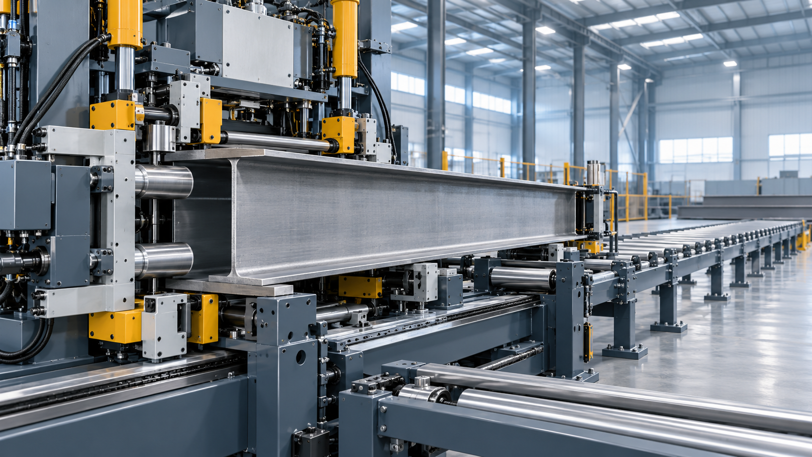
An integrated H-beam assembly machine can improve beam alignment, but only when its mechanical references, clamping sequence, and incoming material condition are matched to the required beam tolerance. Integration does not eliminate alignment error by itself. It reduces the number of uncontrolled handoffs between web positioning, flange positioning, centering, clamping, tack welding, and transfer to the welding stage. That reduction is valuable because each separate adjustment point can introduce cumulative variation.
For fabricated H-beams, alignment is not limited to placing a web between two flanges. It includes web centering, flange parallelism, perpendicularity between web and flange, straightness along the beam length, and the consistency of the root opening before welding. A machine that holds these relationships stable during assembly gives the welding process a more repeatable starting condition. Whether this results in a visibly better final beam depends on what happens before and after assembly as well.
Why assembly alignment affects more than appearance
A beam can appear acceptable after tack welding while still carrying geometry errors that become more difficult to correct after submerged arc welding or other high-heat joining processes. If the web is off-center, the two fillet welds may have unequal geometry. If flange faces are not held parallel, downstream straightening equipment may need to compensate for a condition that originated before welding. If the flange-to-web angle is not close to the drawing requirement, fit-up of stiffeners, end plates, or connection components can be affected.
Alignment also influences welding stability. The welding head, guide mechanism, and seam-tracking arrangement operate most consistently when the joint is located where the production line expects it to be. A varying web position can cause unequal torch offsets or require operator intervention. In a line producing multiple beam sizes, inconsistent fit-up becomes especially disruptive because adjustments intended for one section may not transfer reliably to the next.
The relevant question is therefore not whether automation is inherently more accurate than manual assembly. The useful question is whether the machine can establish, verify, and preserve the specified geometric relationships under the actual range of plate widths, thicknesses, lengths, surface conditions, and production speeds.
What integration changes in the alignment process
In a conventional arrangement, operators may place components on separate rollers, use temporary stops or measuring tools, clamp the flanges, check web position, apply tack welds, and then send the beam onward. Skilled operators can achieve satisfactory results, particularly with stable section sizes and limited volume. The limitation is that positioning, verification, and welding initiation are separated activities. Each movement of the partly assembled beam can alter the fit-up.
An integrated H-beam assembly machine coordinates these functions around a common datum system. Typical arrangements use flange guide rollers or side guides to establish flange position, web guides to center the web, hydraulic or mechanical clamping devices to maintain contact, and a tack-welding or initial joining function that secures the assembly before release. The important engineering feature is not simply that these devices occupy one frame. It is that their motions are referenced to the same machine centerline and controlled in a defined sequence.
When the sequence is properly designed, the machine can:
- bring both flanges into a controlled lateral position rather than relying on approximate placement;
- center or offset the web according to the programmed beam geometry;
- apply clamp force after contact conditions are established, reducing the chance of locking in a skewed part;
- maintain the fit-up while tack welds are made;
- repeat the same datum logic over successive beams without rebuilding temporary fixtures.
This is the main route by which an intergrated h beam assembly machine can improve alignment: it replaces several independent manual references with a coordinated mechanical reference system. The benefit is repeatability, not a guarantee of zero deviation.
The alignment indicators that should be defined before evaluation
“High accuracy” is not a sufficient acceptance criterion for an assembly line. A technical evaluation should identify which measurements matter to the intended beam class and which point in the process owns each measurement. Drawing requirements, applicable fabrication specifications, and the downstream welding procedure should determine the targets.
Web centering is often the first indicator considered. It is the lateral difference between the web centerline and the intended flange centerline. For symmetrical H-beams, this affects weld symmetry and section properties. For deliberately asymmetric built-up sections, the issue is not centering but repeatable placement at the specified offset. Machines with a fixed mechanical centerline can perform well for a narrow family of symmetrical sections; broader product ranges may require controlled adjustment or servo positioning with adequate calibration.
Web-to-flange squareness determines whether the web stands at the required angle to the flange. It should be checked at more than one location along the assembled length, because a local reading near the entry point does not demonstrate that the web remained stable through the machine. Squareness errors can originate from guide wear, uneven clamp loading, twisted plate, or a web edge that is not straight.
Flange parallelism and spacing are relevant where two flanges are assembled around one web. The machine must control both sides without allowing one flange to advance or lag relative to the other. If feed rollers have unequal traction, or if one plate surface carries scale, oil, or burrs, the beam can develop a gradual distortion even when the initial entry alignment is correct.
Longitudinal straightness should not be attributed solely to the assembly machine. It is affected by incoming plate flatness, roller table support, welding heat input, weld sequence, and straightening. The assembly unit can prevent an initial lateral offset or local skew, but it cannot fully correct a flange that has substantial camber or a web with an inconsistent edge.
Root fit-up consistency is particularly important when the assembly stage includes tack welding or directly feeds a welding station. Excessive variation in contact between web and flange can affect weld penetration, bead profile, and welding parameter stability. The evaluation should distinguish between a machine’s nominal positioning range and its ability to maintain contact over real plate tolerances.
Mechanical design matters more than the control screen
Digital position displays, programmable recipes, and automated width adjustment can make setup easier, but they do not compensate for weak structural stiffness or poorly maintained guide elements. Alignment capability begins with the machine frame, guide layout, clamp rigidity, roller arrangement, and the relationship between the entry side and the tack-welding point.
A machine should provide positive and repeatable references for both web and flanges. Free-floating rollers may accommodate minor variation, but they can also allow a component to wander if the contact force is insufficient. Conversely, excessive side-guide force can mark thin material, create drag, or push a flexible web away from its intended position. The appropriate design depends on plate thickness, surface condition, section size, and feed speed.
Clamping sequence deserves close attention. If side guides establish the web position and upper clamps are applied before the web fully seats against the flange, the machine may preserve a gap rather than remove it. If clamp pressure is excessive on a thin flange, local deformation can be introduced before welding. A useful evaluation is to observe the motion sequence slowly: component entry, guide engagement, centering, closing, tack initiation, clamp release, and exit. The process should make geometric sense at every stage, not merely produce an acceptable sample at the end.
Backlash, guide-wheel wear, hydraulic pressure variation, and contamination on roller surfaces are practical sources of drift. For this reason, repeatability tests should include multiple cycles and size changes, not a single beam assembled immediately after setup. A machine may place the first beam accurately but show different results after roller loading, thermal expansion, or repeated clamp movement.
Incoming plate quality sets the ceiling for assembly accuracy
An integrated system aligns plates relative to its own datums; it does not transform unsuitable plate into dimensionally perfect stock. Plate camber, edge waviness, burrs, uneven thickness, residual stress, and twist all influence the final fit-up. A web with a flame-cut edge that varies along its length may contact the flange intermittently even when the centering system is functioning correctly.
Cut quality is especially relevant when web and flange blanks are prepared in-house. The cutting process should produce edges with a geometry and heat effect compatible with the assembly and welding route. For plate preparation across conductive materials, a Gantry CNC plasma cutting machine can be relevant where its cutting capacity, kerf control, and nesting accuracy suit the fabrication process. Its contribution to beam alignment is indirect: consistent blank dimensions and controlled edge condition reduce the variation that the assembly machine must absorb. Precision in blank preparation should not be confused with final beam alignment, but the two are operationally connected.
Material handling also matters. Long flanges supported at too few points can sag before entering the assembly zone. If roller tables are not level with the assembly machine datum, the workpiece can enter under a small angular bias. For heavy sections, the loading method must avoid torsion caused by uneven crane pickup or unsupported transfer. These conditions can make a well-designed assembly machine appear inaccurate when the actual cause lies upstream.
Where integrated assembly has clear limits
Integration is most effective where beam geometry is repeated often enough for stable setup logic to matter and where dimensional variation in incoming material is controlled. It is less decisive when production consists mainly of one-off sections with unusual flange widths, sharply varying web heights, heavily distorted reclaimed material, or frequent manual attachments that interrupt continuous handling.
Very thin plate introduces another limitation. The force needed to guide and clamp material must be balanced against the risk of local buckling. Very thick plate creates the opposite issue: the machine must have sufficient structural capacity to position and hold components without deflection or roller slip. A supplier’s stated thickness range should therefore be separated into two questions: what the machine can physically pass through, and what range it can assemble while meeting the required geometric tolerance.
Welding distortion remains a separate source of final misalignment. Even perfect pre-weld fit-up can change after welding because of shrinkage and heat imbalance. Integrated assembly reduces initial error and supports more consistent welding conditions, but it does not remove the need to evaluate welding sequence, heat input, restraint, and post-weld straightening. Claims that an assembly machine alone guarantees final straightness should be treated cautiously.
A practical acceptance approach
Equipment assessment is stronger when it is based on representative workpieces rather than only on no-load demonstrations. The test material should reflect expected flange widths, web heights, thickness combinations, lengths, and surface conditions. If the production plan includes both narrow and wide sections, both should be tested. If asymmetric sections are required, testing only centered symmetrical beams provides limited evidence.
Acceptance criteria should specify the measurement method, the locations along the beam, and the state of the beam being measured: before tack weld, after tack weld, after main welding, or after straightening. Mixing these stages creates misleading conclusions. The assembly machine should primarily be judged on pre-weld and post-tack geometry, while final beam geometry must be assessed as a result of the entire production route.
It is also useful to require repeatability across a sequence of parts and after a size change. Records should show actual flange spacing, web offset or centering, squareness, and visible fit-up quality. The machine’s adjustment references should be understandable enough that a later setup can be reproduced without relying on an individual operator’s memory.
Integrated assembly technology improves beam alignment when it creates stable datums, maintains fit-up through tack welding, and operates with plate and handling conditions within its design envelope. Its strongest value is not that it replaces measurement, but that it makes measurement results more repeatable. The deciding evidence should be the machine’s ability to hold the required geometry over representative material, repeated cycles, and the full range of sections that the production line is expected to process.
search
Products Navigation
Send Us A Message