




Choosing a sheet metal deburring machine for laser-cut parts
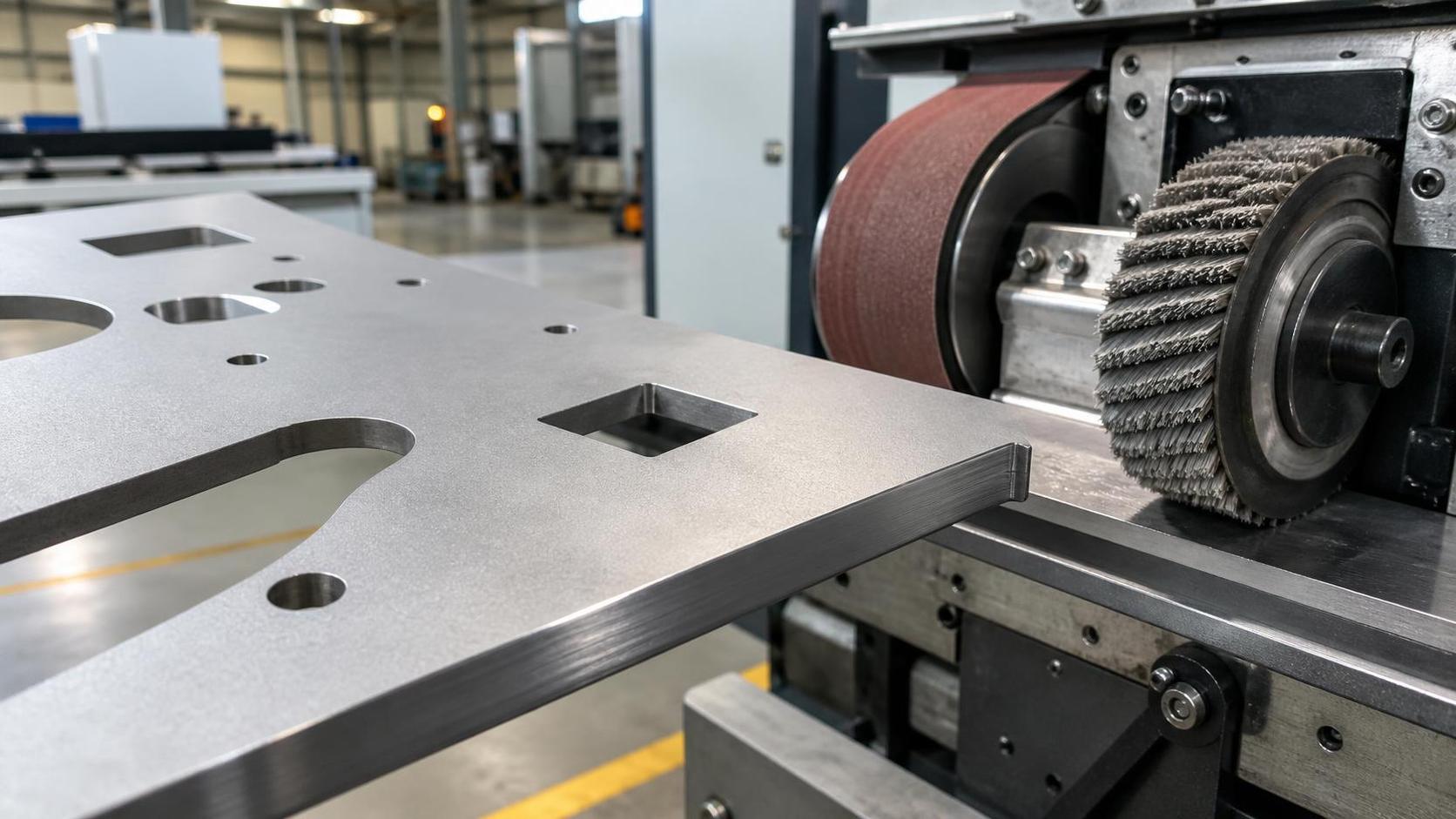
Laser-cut edges may appear smooth yet fail to meet requirements for coating, welding, handling or precision assembly. The deciding issue is not whether a sheet metal deburring machine can remove visible burrs; it is whether it can consistently remove the specific edge condition produced by the laser process without changing critical dimensions, damaging the sheet face, or creating an unstable downstream process.
When selecting equipment for laser-cut components, start by mapping edge quality based on your actual product portfolio. Distinguish between sharp edge breaking, micro-burr removal, stuck dross cleanup, oxide layer treatment and surface finishing. Each requires a different approach. A machine tuned for cosmetic edge rounding on stainless steel might struggle with thick carbon steel parts that have heavy slag along the bottom edge. On the flip side, heavy-duty slag removal units can over-round small holes or scratch workpieces covered with protective film.
Start with the edge condition, not the nominal sheet thickness
Laser cutting does not create one uniform type of burr. Edge condition changes with material grade, thickness, laser power, assist gas, nozzle condition, focal position, cutting speed, contour geometry, and part nesting. A technical evaluation based only on a supplier statement such as “suitable for 0.5–100 mm sheet” is therefore incomplete.
Common laser-cut edge conditions include:
- Fine sharpness with little attached burr: Often found on well-optimized cuts in thinner stainless steel or aluminum. The main requirement may be a controlled edge break rather than material removal.
- Micro-burr on the exit side: A relatively light burr that can interfere with paint adhesion, handling safety, or close-fit assemblies. Brush-based systems are often appropriate if the part is sufficiently supported.
- Heavy dross or slag attachment: More likely on thicker plate, poorly optimized parameters, or difficult contours. It requires a machine with enough contact force and abrasion, not merely soft brushing.
- Oxide scale from oxygen cutting: The issue is not always burr height. A dark oxide layer can affect coating adhesion and some welding operations. Mechanical deburring may reduce loose oxide but does not automatically replace a defined surface-preparation process.
- Heat tint and localized surface discoloration: Relevant for visible stainless parts. Standard abrasive belts can alter the surrounding finish, so the required visual standard must be agreed before equipment selection.
The lower edge is usually the critical side because molten material is expelled downward. Yet parts may need processing on both sides when handling safety, coating consistency, or symmetrical edge radiusing is specified. A single-pass machine that treats only the lower face may be sufficient for hidden structural components, but not for exposed enclosures, food-processing equipment, or parts that are manually assembled on both sides.
Match the abrasive architecture to the required result
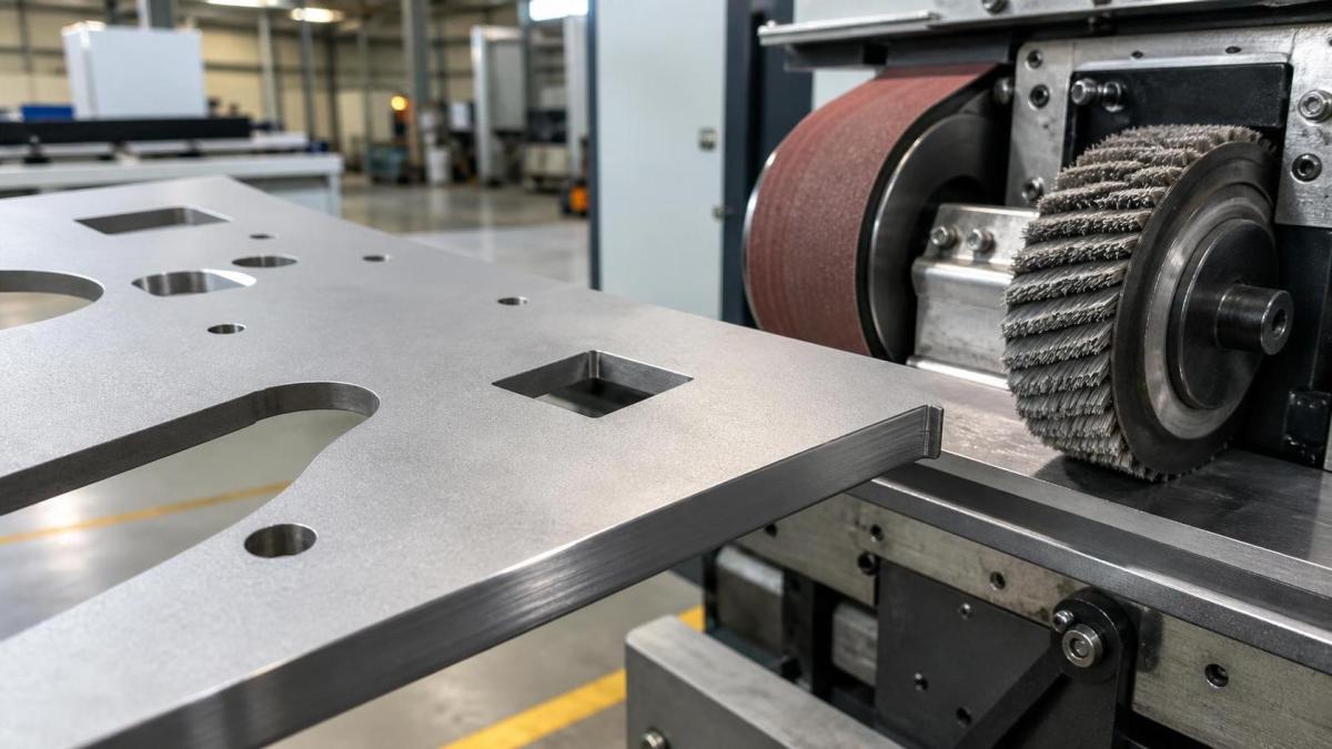
“Deburring” covers several machine architectures that behave very differently. The appropriate configuration depends on whether the primary objective is slag removal, uniform edge rounding, face finishing, or a combination of these outcomes.
Wide abrasive belt systems are effective for removing heavier burrs, leveling cut-edge irregularities, and correcting surface defects over broad areas. They are most useful where material removal is acceptable and the workpiece is stable. Their limitation is directional action: a belt can produce inconsistent treatment around internal holes, narrow tabs, and contours running parallel to the belt direction. Excessive pressure can also reduce small feature dimensions or leave visible scratch patterns.
Rotary brush or cross-belt brush systems are generally better suited to multidirectional edge rounding. The abrasive filaments contact external contours, internal holes, slots, and complex laser-cut geometry from multiple directions. This makes them valuable for parts requiring a repeatable radius rather than simple burr knock-off. However, brush media loses cutting effectiveness as it wears, and its result depends heavily on brush density, grain size, rotation speed, workpiece feed, and compression setting.
Combination machines commonly use a contact drum or wide belt for primary burr or slag removal followed by one or more brush stations for edge rounding. This arrangement is often the most flexible option for mixed laser-cut production, but it should not be selected merely because it has more stations. Each station needs a defined purpose. Adding a strong initial belt to a process that only needs edge softening can increase consumable cost and reduce control over delicate parts.
Disc, planetary, or oscillating brush arrangements can provide good contour access and more uniform treatment around holes and irregular shapes. Their suitability should be verified with the smallest holes, narrowest slots, and thinnest webs in the actual part portfolio. A part can emerge with excellent outer-edge rounding while retaining burrs inside apertures that are too small for the abrasive media to enter effectively.
For parts requiring only a safety edge break, the desired result should be defined as a small, controlled edge radius or chamfer—not “maximum deburring.” The latter language encourages excessive processing. In technical terms, the acceptable range should address residual burr, edge radius, surface scratch level, and permitted dimensional change.
Evaluate the hardest representative parts rather than average parts
A convincing demonstration should include more than flat rectangular coupons. A laser-cut production mix often contains features that expose the real limitations of a deburring line: perforated panels, small internal holes, louvers, narrow strips, long thin parts, sharp corners, parts with raised tabs, and sheets with protective film.
The sample set should include the material and thickness range actually being processed, with examples of the poorest acceptable cut quality rather than only optimized cuts. It is useful to compare the untreated and treated state at several locations: the lower cut edge, upper edge, internal holes, tight radii, narrow bridges, and corners. Visual inspection alone is insufficient where coating or assembly performance matters. A process validation should also consider edge-radius consistency, residual dross, flatness, scratch direction, and any change to critical openings.
Part support deserves particular attention. Small workpieces can rotate, lift, or catch under abrasive heads. Thin sheet can flutter. Perforated pieces may flex under belt pressure. Machines may use vacuum tables, magnetic conveyors, roller systems, or combinations of these. None is universally suitable:
- Magnetic conveyance is practical for ferrous steel but cannot hold aluminum, copper, or stainless grades with low magnetic response.
- Vacuum support can help with thin non-ferrous sheet, but performance depends on part coverage, leakage through holes, and workpiece geometry.
- Roller conveyors can accommodate heavier plates but may be unsuitable for small parts without carriers or fixtures.
When material mix includes carbon steel, stainless steel, and aluminum, the support method is only one concern. Abrasive contamination must also be controlled. Carbon-steel particles embedded in tools or conveyed onto stainless surfaces can create later corrosion problems. Separate consumables, controlled cleaning, and a documented changeover method may be necessary where surface integrity is important.
Laser cutting quality and deburring capacity must be assessed as one process
A deburring machine should not become a substitute for poor cutting conditions. If the laser process produces thick, uneven dross across a frequent production range, the first question is whether cutting parameters, gas purity, nozzle alignment, focus control, or consumable condition should be corrected. Mechanical post-processing can compensate for a limited range of variation, but designing the entire finishing process around avoidable slag increases abrasive consumption, cycle time, dust load, and the risk of part damage.
This is particularly relevant when evaluating high-speed fiber laser capacity. A machine with high positional accuracy and narrow kerf can generate parts with clean geometry, but edge quality remains dependent on the relationship between material, thickness, power, gas, and cutting parameters. For example, a fiber laser system with 1500 mm by 3000 mm cutting capacity may be an appropriate upstream source for varied fabricated components, yet the deburring line should be sized according to the actual mix of lower-edge conditions—not its maximum laser travel speed.
Where cutting and finishing equipment are being planned together, the production route should be reviewed from nesting to final handling. The Steel Plate cnc fiber laser cutting machine is specified with optional power levels from 1500 W to 6000 W or more and supports common metal materials including carbon steel, stainless steel, aluminum alloy, copper, and titanium alloy. That breadth is useful for flexible cutting, but it also means a downstream deburring specification must distinguish material families and thickness bands rather than assume a single abrasive recipe will work for all parts.
Define edge-radius requirements before comparing throughput claims
Throughput figures can be misleading unless the required finish is identical. A machine can process a large area per hour when it only removes loose burrs. The same machine will process less area when a specified edge radius must be developed on both outer contours and internal cutouts. Heavy slag removal, double-sided treatment, and parts requiring multiple passes further change effective capacity.
A useful capacity model considers:
- usable conveyor width rather than maximum machine width;
- average nesting density and the percentage of open sheet area;
- feed rate needed for the required edge condition;
- number of passes for top and bottom surfaces;
- loading, unloading, part separation, and orientation time;
- rework generated by incomplete deburring or over-processing;
- abrasive change intervals and setup time between material families.
For small-batch, high-mix work, fast and repeatable setup changes may matter more than maximum headline throughput. Controls should allow recipes for material type, thickness, burr severity, abrasive station settings, conveyor speed, and required finish level. A saved recipe is valuable only if operators can verify that the installed abrasive media still matches the programmed condition. Brush wear, belt loading, and variation in incoming laser-cut quality all affect the result.
Automation should be judged in the same way. Automatic loading and unloading can reduce handling effort for stable, repeatable panels, but it may add little value when the work mix contains many small, irregular, or delicate parts that need manual orientation. The practical question is whether automation preserves part identification, avoids surface damage, and maintains flow into bending, welding, powder coating, or assembly.
Material compatibility is more than “ferrous versus non-ferrous”
Carbon steel generally tolerates more aggressive processing when the requirement is to remove lower-edge slag before welding or coating. Stainless steel may require closer control of scratch pattern, contamination, heat coloration, and edge consistency. Aluminum is softer and can load abrasives more readily; it is also more easily marked or distorted. Copper and titanium alloys introduce their own handling and contamination concerns, particularly where parts have cosmetic or functional surface requirements.
Protective film creates another limitation. Some brush processes can treat edges while preserving a film-covered face under controlled conditions, but film lifting near cut edges, adhesive transfer, and trapped debris should be tested. A machine should not be selected based on a demonstration using unfilmed sheet if normal production uses coated, brushed, or film-protected material.
Coated sheet requires special caution. Deburring after coating can expose bare metal at the edge, while deburring before coating may be necessary to obtain adequate coating coverage and avoid sharp points. The correct sequence depends on the coating system and the edge specification. A finishing machine cannot independently establish coating compatibility; that must be validated with the downstream finishing process.
Consumables, dust extraction, and maintenance determine process stability
Purchase price is a weak indicator of operating cost. Abrasive belts, brush media, contact elements, conveyor components, vacuum systems, and extraction filters all influence the real cost per part. The key issue is not simply abrasive life in hours, because workpiece mix and required edge condition change the rate of consumption. Heavy dross removal on thick oxygen-cut carbon steel can consume media very differently from light edge rounding on thin stainless sheet.
Dust extraction is a technical requirement, not an accessory to be decided after installation. Grinding dust, metallic fines, abrasive particles, and residue from coatings or film adhesives require an extraction system designed for the machine’s process. The system must be compatible with the material being processed and with applicable workplace safety requirements. Aluminum and other combustible metal dusts demand particular care in system design, housekeeping, segregation, and risk assessment. Equipment suppliers should clearly define extraction volume, duct connection requirements, and any restrictions on materials or processes.
Maintenance access affects whether a theoretically capable machine remains capable in regular production. Review the time and access required to change belts and brushes, clean internal dust accumulation, inspect conveyors, adjust support systems, and replace wear components. Ask how the machine indicates media wear or process drift. A simple and visible maintenance routine is often more valuable than a complex arrangement that is difficult to inspect.
Acceptance criteria should be written around the downstream operation
The correct deburring result depends on what follows. A welded bracket may only need removal of dangerous sharpness and loose slag. A powder-coated enclosure may need a consistent edge radius to improve coating coverage. A precision assembly may require burr-free holes without altering fit. A visible stainless panel may require a controlled surface finish in addition to edge conditioning.
Acceptance criteria should therefore state the functional target in measurable terms where possible: permitted burr condition, required edge-radius range, treatment of internal holes, allowable surface scratch level, part flatness, dimensional tolerance at critical features, and the surfaces to be processed. If both sides are required, this should be explicit. If heavy dross is acceptable on hidden areas but not on assembly faces, that distinction should also be defined.
The most reliable selection is rarely the machine with the highest nominal capacity or the largest number of abrasive heads. It is the configuration that produces the required edge condition on the most difficult recurring laser-cut parts, with controllable dimensional impact, manageable consumable use, and a process that remains stable as material and cut quality vary. That is the point at which a sheet metal deburring machine becomes a controlled manufacturing operation rather than an uncertain finishing step.
search
Products Navigation
Send Us A Message