




How a 7-Axis Railway Welding Robot Extends Reach on Long Fabrications
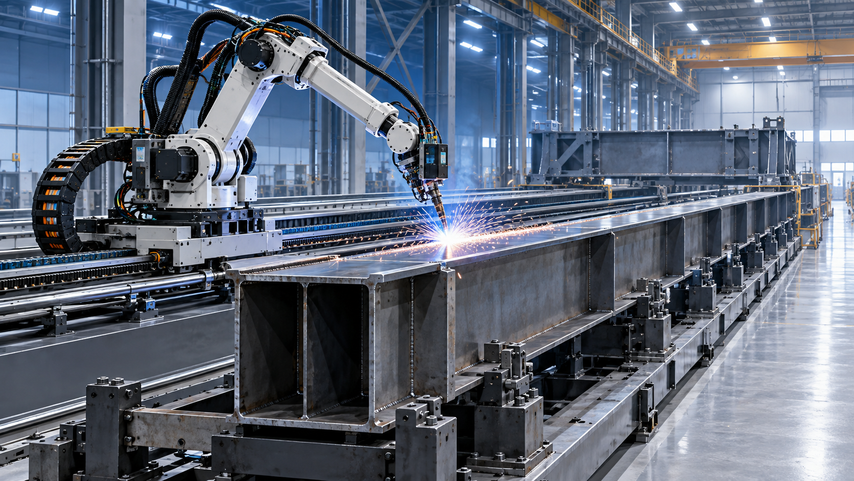
A 7-axis railway welding robot extends reach not by making the welding arm intrinsically longer, but by adding a controlled linear travel axis beneath or beside the robot. The robot moves along a rail while its six articulated axes maintain torch orientation, travel angle, stand-off, and weld-path accuracy. For long beams, frames, box sections, bridge members, ship blocks, pressure-vessel components, and other oversized fabrications, this changes the production problem from repeated workpiece repositioning to coordinated robot-and-rail motion.
The practical value is not simply more metres of travel. It is the ability to keep a large fabrication fixed in a stable fixture while the welding system reaches successive joints along its length. That can reduce crane dependency, shorten non-welding time, preserve datum control, and make welding quality less dependent on how often an assembly must be moved. The benefit is strongest where a conventional six-axis cell would otherwise require several setups to complete welds on one long workpiece.
The seventh axis solves a coverage problem, not every welding problem
A standard six-axis robot has a defined working envelope. It may reach around corners, approach a joint from different angles, and manipulate a torch around moderately complex geometry, but it cannot economically cover a fabrication that is substantially longer than its cell envelope. Extending the arm reach is rarely the most efficient answer: a larger robot brings a larger footprint, different stiffness characteristics, and higher capital cost, while still leaving access limits at the far ends of the part.
In a 7-axis railway welding robot configuration, the external linear axis becomes part of the robot’s coordinated kinematics. The controller does not treat rail travel as a separate positioning operation. During a programmed weld, it can coordinate carriage position with the arm’s movements so that the torch follows the intended seam at a controlled speed and orientation.
This distinction matters. A manually repositioned robot can reach multiple stations, but each move creates a stop-start sequence: retract, travel, verify position, recover the correct coordinate frame, and restart. A coordinated rail-mounted robot can maintain a continuous welding strategy over longer seam segments, provided that cable management, seam tracking, fixture accuracy, and safety zoning have been designed for the full travel length.
The rail axis is especially useful when the part is long in one dominant direction. Typical examples include:
- longitudinal stiffeners and seams on fabricated plate structures;
- multi-bay frames and structural assemblies;
- long box girders, chassis rails, and heavy equipment booms;
- repetitive brackets, ribs, or attachments distributed along a beam;
- large fabricated sections where rotating or lifting the workpiece between weld zones would be slow or difficult.
It is less compelling where the workpiece is compact but geometrically congested, where production consists mainly of short and highly variable jobs, or where fit-up is too inconsistent for automated welding to recover reliably. A linear axis expands coverage; it does not correct poor joint preparation, unstable assemblies, or inaccessible weld positions.
Reach changes the production flow around the fabrication
For a long fabrication, the conventional workflow often involves moving the part through several welding locations or rotating it to present each weld to a fixed robot. That can be appropriate when parts are light enough to handle quickly and when different operations require dedicated stations. It becomes inefficient when the assembly is heavy, flexible, safety-sensitive to lift, or long enough that every repositioning affects alignment.
A rail-mounted robot permits a different arrangement: the fabrication remains on a long fixture, while the robot serves defined zones along that fixture. The result is not necessarily one uninterrupted weld from one end of the part to the other. In many projects, the more useful outcome is a reduction in handling events between groups of welds. The robot can complete a set of accessible seams in one zone, travel to the next, and continue without releasing the workpiece from its locating references.
That stability matters because repeated lifting and reclamping can introduce small shifts that accumulate across a long assembly. Even when the weld itself remains acceptable, inconsistent part location can increase programming adjustments, inspection effort, and rework risk. Keeping the fabrication in one controlled datum system makes it easier to link upstream fit-up, robotic welding, and downstream dimensional verification.
There is also a scheduling effect. Cranes and rotators are often shared resources. If a welding operation repeatedly needs them for repositioning, its timing becomes dependent on surrounding activities. A rail system does not eliminate the need for material handling, but it can remove lifting from the middle of the welding sequence. That reduces the number of operational handoffs that can interrupt a planned production window.
Rail length should be defined from the usable welding envelope
One frequent planning mistake is to specify rail length based only on the nominal length of the fabrication. A 12-metre part does not automatically require a 12-metre robot rail. Nor does a 12-metre rail guarantee that all welds on a 12-metre part can be completed.
The relevant calculation starts with the robot’s usable working envelope at each carriage position. The arm must reach the joint while maintaining an acceptable torch angle, stick-out, cable posture, collision clearance, and welding orientation. End zones require particular attention because the robot may need clearance beyond the physical end of a seam to approach, initiate, terminate, or move around local features.
Rail travel therefore needs to account for more than part length:
- the length and location of actual weld seams;
- fixture overhang and loading clearances;
- robot reach available on both sides of the carriage centreline;
- approach and retreat space at the ends of each weld;
- service access, energy chain travel, and mechanical end stops;
- future product variants that may be longer, wider, or differently configured.
A digital layout review is valuable before the system footprint is frozen. The review should include the robot model, positioner or fixture geometry, rail position, torch package, wire feeder arrangement, safety fencing, and the largest credible fabrication envelope. It should test not only whether the torch can touch the seam, but whether it can reach that seam with a stable and repeatable welding posture.
Reach simulation also exposes a second constraint: access does not equal productivity. A robot may technically reach a joint near the limit of its envelope, yet move with reduced freedom, poor cable routing, or insufficient clearance for seam tracking hardware. The useful design objective is repeatable access with process margin, not the maximum theoretical reach shown in a catalogue diagram.
Long-travel accuracy depends on the whole mechanical chain
When a robot is mounted on a linear rail, weld quality depends on the relationship between the robot base and the workpiece over the entire length of travel. A highly accurate robot cannot compensate indefinitely for rail alignment errors, floor settlement, loose anchoring, carriage play, or a fixture that varies in height from one end to the other.
The issue is not that every rail must meet an abstract precision target. The required accuracy depends on joint type, welding process, seam width, use of adaptive tracking, and permitted variation in final fabrication dimensions. Narrow-groove joints, fillet welds near visible surfaces, and welds with strict positional tolerances demand more control than broad, forgiving joints. What matters is that rail geometry, fixture datums, and programmed workpiece coordinates remain consistent enough for the chosen welding process.
For long installations, project planning should address rail foundations and alignment as installation-critical work rather than a secondary civil task. The rail needs an adequately stable support structure, verified straightness and level, reliable anchoring, and a method for confirming positional repeatability after installation. Thermal movement, debris accumulation, and impact exposure should also be considered where the cell is installed in heavy fabrication areas.
Calibration must cover the external axis as well as the robot arm. The controller needs an accurate relationship between the robot base frame, rail coordinate system, fixtures, and workpiece reference points. If the workpiece is loaded at different stations or in different fixture modules, each arrangement requires a controlled coordinate strategy. Treating all long parts as though they share one fixed reference frame can create avoidable offsets.
Welding continuity is only useful when fit-up is controlled
Long fabrications present a recurring automation challenge: the nominal CAD model may be straight, while the actual assembly contains accumulated variation from cutting, tack welding, thermal distortion, and clamping. A robot can travel smoothly along its rail and still miss the intended joint if the seam moves relative to the programmed path.
This is why a 7-axis arrangement should be considered alongside fit-up control, not as a substitute for it. Robust applications typically define tolerances for component location, root gap, tack position, joint cleanliness, and allowable distortion before welding begins. Where variation cannot be reduced sufficiently, the system may need touch sensing, through-arc seam tracking, laser vision, or a combination of these methods. The appropriate choice depends on the joint, welding process, surface condition, and cycle-time requirement.
Seam tracking has limits. It can compensate for local deviations within its operating range, but it cannot make an incorrectly assembled joint weldable. It also adds setup, validation, and maintenance requirements. On parts with scale, spatter, primer, inconsistent gaps, or irregular tack welds, sensor reliability needs to be assessed under real production conditions rather than assumed from a demonstration.
Long welds also require deliberate control of heat input and sequence. A rail-mounted robot makes it easier to access distant weld locations, but it may encourage a simplistic “weld from one end to the other” approach. Depending on part stiffness and joint arrangement, that sequence can increase distortion. Intermittent welding, back-step strategies, balanced weld sequences, controlled cooling intervals, or fixture restraint may be needed to meet dimensional requirements. The correct sequence is a fabrication-engineering decision, not a default robot program.
Upstream cutting and edge preparation affect robotic utilisation
Robotic welding time is often discussed in terms of arc-on time, but the reliability of the welding cell begins earlier. Inconsistent cut edges, incorrect bevels, burrs, and poor repeatability in hole or slot location can all reduce the value of a long-travel welding system. When the joint arrives outside its expected geometry, the robot either needs adaptive recovery or human intervention.
For long plate-based fabrications, cutting equipment should be selected with the downstream fixture and welding process in mind. A Gantry CNC plasma cutting machine can be relevant where large conductive-metal plates must be cut before forming and assembly, particularly because gantry travel and nesting capability support processing of long blank layouts. Its value to welding automation is not the cutting speed alone; it is the ability to deliver parts with repeatable geometry that can be located consistently in downstream fixtures. Edge condition still needs to be matched to the welding procedure, including removal of oxide, dross, or contaminants where required.
Project plans should therefore connect cutting tolerances, forming variation, tack-welding practice, fixture design, and robot sensing requirements. Separating these decisions by department can lead to an expensive welding cell being asked to absorb variation introduced upstream.
Safety zones become more complex as travel distance increases
A fixed robot cell has a relatively stable hazardous envelope. A rail-mounted robot creates a moving hazardous zone along the length of the installation. This affects fencing, interlocked access points, cable routing, material loading, and the way personnel enter the area for tack welding, inspection, cleaning, or maintenance.
The safety concept must distinguish between automated welding, manual preparation, fault recovery, and material loading. A long rail can create situations in which one end of the cell is active while personnel need access at the other. Whether this can be permitted depends on the risk assessment, safeguarding architecture, operating mode, and applicable local requirements. It should not be assumed that physical separation by distance is sufficient.
Fume extraction also deserves early attention. Welding over a long fixture can shift the fume source significantly during a cycle. A single fixed extraction hood may be effective at one rail position and inadequate at another. Source capture, movable hoods, segmented extraction, or enclosure strategies should be evaluated against the actual weld locations and operating sequence.
What a workable implementation plan looks like
The strongest applications are defined around a stable family of parts rather than a generic ambition to automate welding. The fabrication family should share enough commonality in length range, joint design, loading method, and quality requirements that one rail-and-fixture concept can serve it without excessive changeover work.
Before committing to a 7-axis railway welding robot, the project should establish the longest and widest workpiece envelope, the welds that must be automated, the welds that remain manual, expected part variation, target throughput, and the available floor length. It should also identify whether the fabrication can remain in one fixture through the required weld sequence. If frequent flipping or major rotation is unavoidable, a rail-mounted robot may need to be combined with positioners, rotators, or multiple access stations.
Acceptance criteria should extend beyond a demonstration weld. They should include repeatable loading location, reach to all designated seams, cycle time with realistic inter-weld travel, weld quality against the applicable procedure and inspection requirements, sensor recovery where used, safe access during normal operation, and maintainability of the rail, carriage, torch package, and cable system.
The central planning judgment is straightforward: a seventh axis creates value when it removes non-value-added movement without creating a new coordination burden. On long, heavy, or handling-intensive fabrications, the ability to move the robot instead of the workpiece can materially improve flow and control. But the result depends on disciplined fixture design, realistic reach validation, stable incoming part quality, and a safety concept designed for a moving cell—not merely on adding rail length to a conventional robot.
search
Products Navigation
Send Us A Message