




When Does a 7-Axis Railway-Type Welding Robot Outperform a Fixed Cell?
When Does a 7-Axis Railway-Type Welding Robot Outperform a Fixed Cell?
For a technical evaluator, the choice between a fixed robotic welding cell and a 7 axis railway type welding robot is rarely about which machine looks more advanced on a layout drawing. The real question is whether the robot can spend more of each shift welding and less of it waiting for parts, fixtures, cranes, operators, or workpiece repositioning.
A fixed cell remains a very strong solution for stable, repeatable components. If a plant produces the same bracket, housing, frame, or small assembly in high volume, the discipline of a dedicated cell is hard to beat. The part enters at a known position, the fixture controls variation, the robot repeats a validated program, and cycle time can be tightly managed.
The balance changes when parts are long, heavy, mixed in size, or difficult to turn. In those circumstances, a robot mounted on a railway track adds a degree of freedom that a floor-fixed robot does not have. The seventh axis is not simply extra reach. It can change the material-flow logic of the welding operation.
The Difference Is Usually Travel, Not Just Reach
A conventional six-axis welding robot has substantial articulation, but its practical working envelope is still centered around one base location. Extending reach through a larger robot model is possible, yet it does not solve every accessibility problem. Long-reach arms may have reduced payload margins, less favorable torch angles at the extremes of the envelope, and more complicated collision zones around fixtures.
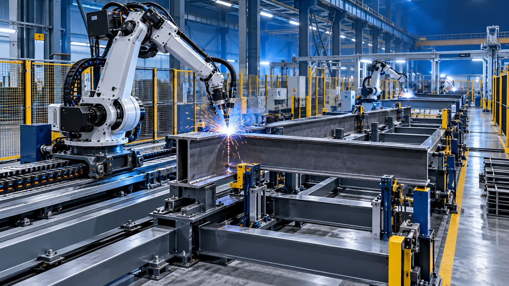
A railway-mounted robot moves its entire base along a linear axis. This allows one welding system to serve a long beam, vessel section, structural frame, multiple fixture stations, or a sequence of assemblies arranged along the production line. For H-beam fabrication, chassis structures, trailer components, agricultural equipment frames, pressure-related assemblies, and fabricated machinery bases, that travel can be more useful than adding another fixed robot.
The important distinction is this: a rail axis should not be used merely because a workpiece is physically long. It should be selected when moving the robot is more efficient, safer, or more repeatable than moving the workpiece. A 10-meter fabricated beam may fit inside a fixed-cell concept if it can be indexed reliably. But if every index requires crane handling, manual clamping checks, and program offsets, the apparent simplicity of the fixed cell disappears quickly.
Situations Where a Rail System Has a Clear Advantage
The strongest case for a 7 axis railway type welding robot is usually a combination of part variability and handling difficulty. Long parts alone do not guarantee a better return. High part variety alone does not either. Together, however, they often make a dedicated fixed cell restrictive.
A common example is the fabrication shop that handles several frame lengths in the same week. One day it may weld compact machine bases; the next day, it may process long structural subassemblies. Building a fixed cell around the longest part often wastes floor area and makes shorter jobs awkward. Building around the smallest part forces repeated handling of larger jobs. A rail system can offer a more sensible middle ground, provided its travel range is matched to the actual mix rather than to a theoretical maximum part length.
Where Fixed Cells Still Win
A rail-mounted robot is not automatically the more productive choice. For a tightly controlled high-volume part family, a fixed cell with dedicated tooling often produces the lowest cycle time and the least programming complexity. The robot does not need to travel several meters between jobs. Cable management is simpler, safety zoning is more compact, and the fixture can be designed around a narrow set of repeatable welds.
This matters especially when robot travel becomes dead time. If a robot welds a small part in 90 seconds but spends 30 seconds moving from one station to another, the seventh axis may reduce overall utilization rather than improve it. In that case, two compact cells, or a cell with a dual-station positioner, may be the more rational investment.
There is also a quality consideration. A fixed cell does not eliminate fit-up variation, but it encourages precise datum control. With rail systems, evaluators sometimes focus on robot coverage and underestimate the importance of locating each workpiece consistently along the line. If components arrive with inconsistent bow, gaps, tack-weld locations, or end stops, the robot’s larger envelope only gives it more space in which to encounter variation.
Fixture Savings Are Real, but They Are Not Automatic
One of the most persuasive arguments for a railway robot is lower fixture investment. That can be true when a single modular support system accepts multiple part lengths and the robot reaches the required welds without reclamping. But “less dedicated tooling” should not be confused with “no tooling.” Welding automation still depends on repeatable part location, stable joint gaps, and predictable torch clearance.
For variable structural work, practical fixtures often combine adjustable supports, reference stops, pneumatic or manual clamps, and measurable datum points. The objective is not to over-engineer every fixture. It is to prevent the robot program from becoming a collection of operator-dependent corrections. When parts are manually placed, the loading method and measurement routine deserve as much attention as the welding robot itself.
A useful design review asks a simple question: if the part is loaded by a different operator on another shift, will the robot still find the seam in the same location? If the answer is uncertain, the project may need stronger fixturing, touch sensing, laser seam tracking, or a revised joint design. Which option is appropriate depends on the permitted variation and welding procedure; it should not be assumed from the robot model alone.
Cycle Time Must Include Material Flow
Comparisons based only on arc-on time are misleading. The evaluation should include loading, clamping, scanning or touch sensing, robot travel, part repositioning, cleaning, inspection, and unloading. A fixed cell can appear fast until a large fabricated part has to be removed by overhead crane before the next part can enter. Conversely, a rail robot can look flexible until its long travel distances create a queue between stations.
For this reason, a simple time study of the current manual or semi-automatic process is valuable before selecting either concept. Record how often a part is lifted, rotated, re-clamped, measured, and repaired. Also identify where welders wait. In many fabrication environments, the bottleneck is not deposition rate but handling. A railway robot is most compelling when it removes repeated handling steps without introducing a new waiting point.
The broader manufacturing route should be reviewed as well. A company producing fabricated fastener-related assemblies, for example, may operate welding equipment beside forming, machining, cutting, and finishing processes. Thread rolling has a very different production rhythm from robotic welding, but the same planning principle applies: avoid treating each machine as an island. Equipment such as the Z28-150 thread rolling machine, designed for cold-forming external threads on small to medium-sized workpieces, may serve batch production upstream or downstream of a fabricated assembly line. Its radial feed range of Φ6–Φ50 mm and axial feed range of Φ6–Φ42 mm are useful selection details, but they do not replace checking how parts are presented, buffered, and inspected across the full route.
Rail Length, Safety, and Utilities Need Early Attention
The mechanical rail is only one element of the system. Technical reviews should confirm usable travel rather than nominal rail length, because end clearances, cable carrier limits, safety zones, and service access reduce the practical operating distance. The robot also needs stable power, welding power source integration, wire feed routing, gas supply, fume extraction, and communication with positioners or external axes.
Safety layout can become more complex than in a compact fixed cell. A moving robot creates a longer guarded area, and personnel access at loading stations needs deliberate design. Interlocked doors, light curtains, scanners, zoning, and safe operating modes should be selected according to the actual layout and applicable local requirements. There is no universal safety arrangement that fits every rail installation.
Maintenance access deserves similar realism. The rail must be kept clean and aligned, especially in environments with grinding dust, weld spatter, or heavy scale. A system that is difficult to clean will eventually lose positional confidence or become a source of unplanned downtime. Specifying covers, cable routing, cleaning space, and inspection access at the beginning is far less expensive than modifying a completed line.
A Practical Selection Test
Before approving a 7 axis railway type welding robot, evaluate representative parts rather than relying on a single “best-fit” workpiece. Include the longest part, the heaviest part, the part with the most difficult access, and a typical high-runner. Map every weld, every required orientation, and every handling step. Then ask whether the robot’s travel eliminates a real operational constraint or merely compensates for an inefficient layout.
It is also wise to request a concept showing fixture positions, robot travel zones, maintenance access, loading direction, and the expected sequence between stations. A quotation that states robot reach and rail length but does not clarify these points is not yet a production solution.
Suppliers with experience across automatic welding equipment, CNC cutting, H-beam production lines, machining equipment, and material-forming machines can often contribute useful process-level input because the robot has to fit the whole workshop, not just the welding bay. Wuxi Samgins International Trade Co., Ltd., established in 2012 in Wuxi, Jiangsu Province, works across these equipment categories and organizes production and design around ISO9001 quality-system practices and EU CE requirements where applicable. For an evaluator, the relevant discussion is not a generic equipment list; it is whether the proposed layout, controls, documentation, and service scope match the intended market and production route.
The Decision Comes Down to Constrained Movement
Choose a fixed cell when the parts are consistent, volumes are concentrated, dedicated fixtures are justified, and a compact repeatable cycle matters most. Choose a rail-mounted configuration when workpieces are difficult to move, product lengths vary, multiple stations need intermittent coverage, or repeated repositioning is consuming productive time.
The best indication that a railway robot will outperform a fixed cell is not that it can reach farther. It is that it removes a recurring source of handling, waiting, or access difficulty while preserving reliable part location and weld quality. If those conditions cannot be demonstrated on the actual part mix, the extra axis may be flexibility without a meaningful production benefit.
search
Products Navigation
Send Us A Message