




What to Verify Before Choosing a 9-Axis Welding Robot Supplier for Production
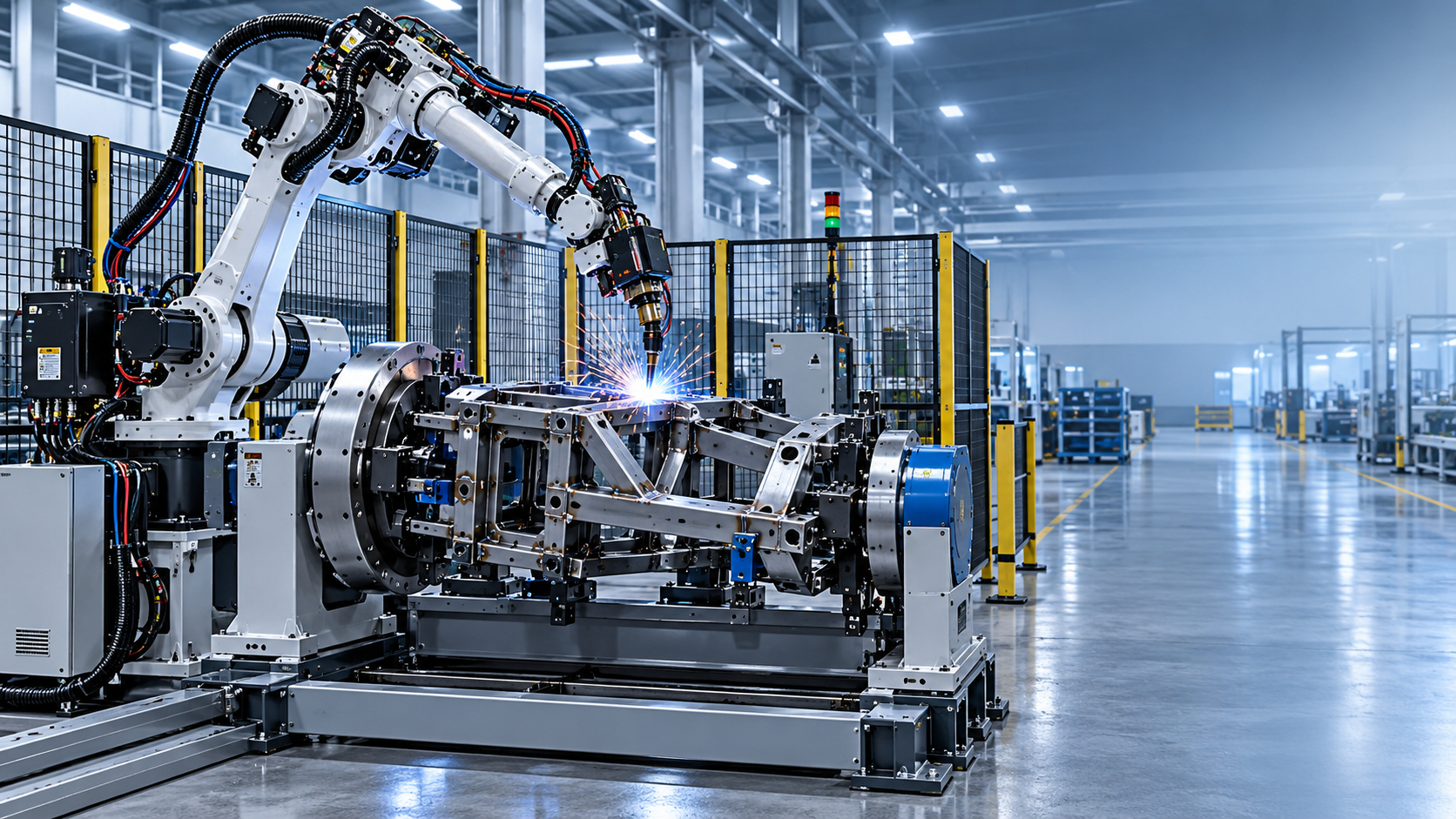
A 9-axis welding robot can solve access and positioning problems that a standard fixed robot cell cannot, but the added motion also makes supplier selection more demanding. The first question is not whether a supplier can quote a robot. It is whether the proposed system can weld your actual parts repeatedly, at the required quality level, within the available cycle time and floor space.
When comparing a 9 axis welding robot supplier, the lowest equipment price is rarely the most useful starting point. A complete welding cell depends on robot reach, external axes, fixture accuracy, part handling, welding process settings, safety design, programming, and service response. A quote that looks attractive because it excludes tooling, positioners, commissioning, or spares may become the more expensive option after installation.
A practical selection process begins with the workpiece, not the robot brochure. Provide part drawings, material grade, thickness range, joint type, weld length, production mix, expected daily output, acceptable weld appearance, and the way parts are loaded and unloaded. A capable supplier should use this information to explain the recommended cell layout and its limits. If the discussion stays at payload, reach, and a headline axis count, the technical evaluation is incomplete.
Confirm What “9 Axis” Means in the Proposed Cell
“9-axis” is often used to describe a welding system with a six-axis robot plus three external axes. Those external axes may be a rotating positioner, a turning and rotating fixture, a linear track, or another coordinated motion arrangement. The same total axis count can therefore produce very different production capabilities.
Ask the supplier to identify every axis in the system and state its function. For example, a robot mounted on a track may travel along a long workpiece, while a two-axis positioner may rotate and tilt a component so that more welds can be completed in a favorable welding position. The remaining external axis might control a tailstock, a second fixture station, or another handling movement. This matters because each layout affects access, welding orientation, loading time, guarding, cable routing, and cost.
Do not assume that more axes automatically mean better welds. Extra motion is valuable when it keeps the torch at the correct angle, allows continuous welding around complex geometry, or removes repeated manual repositioning. For simple, flat, low-variation parts, an elaborate coordinated cell can add capital cost and programming complexity without delivering proportional value. The supplier should explain why each axis is needed for your parts.
Test the Proposal Against Real Part Geometry
A simulation, layout drawing, or weld-access study should be part of the technical offer for complex workpieces. It should show the robot’s reachable weld paths, torch orientation, likely collision points, fixture clearance, cable interference, and the clearance required when the part rotates. This is particularly important for frames, tanks, pipe assemblies, structural members, fabricated housings, and parts with internal corners or deep features.
Reach alone is not enough. A robot may physically reach a joint but still be unable to maintain a stable torch angle, correct stick-out, or suitable travel direction. The result can be an awkward weld sequence, frequent repositioning, or manual touch-up. Ask how the cell will handle inaccessible joints and whether any welding must remain manual. A serious answer includes the reason, not a broad claim that the robot can weld the entire part.
Part variation deserves the same attention. If fabricated components arrive with dimensional variation, a fixed program may not follow the seam accurately. The supplier should discuss whether the proposed process relies on precise fixturing, touch sensing, seam tracking, adaptive programming, or a combination of these methods. These are not interchangeable features. Touch sensing can locate defined reference points; seam tracking is intended to follow a weld joint during welding; accurate fixtures reduce the need for either. Select the level of correction that matches the variation in your incoming parts.
Evaluate the Positioner as Part of the Robot System
In many automated welding cells, the positioner determines whether the robot can weld efficiently. It presents the joint to the torch, supports the workpiece during rotation, and can allow welding in a more controlled orientation. Treat it as a production-critical machine, not as an accessory added after the robot is selected.
The supplier should calculate the complete rotating load: the part, fixture, clamps, adapters, and any attached tooling. More importantly, check the center of gravity and eccentricity, not just the nominal load rating. A workpiece that is offset from the rotation center creates a different mechanical condition from a centered load of the same weight. Oversights here can lead to poor rotational stability, reduced usable capacity, difficult fixture design, or unsafe operating conditions.
For an automatic welding center, a Welding positioner with variable-frequency controlled rotation and suitable tilt travel can help maintain a consistent weld orientation. Available capacities span from light workpieces to heavy fabricated assemblies, while the appropriate model depends on the actual rotating mass, part envelope, center of gravity, required rotation speed, and fixture design. Some configurations also use head-and-tailstock or lifting arrangements where long or irregular parts need better support.
Ask to see the proposed worktable diameter, rotation and tilting range, speed-control method, fixture mounting arrangement, and the maximum swept diameter when the part is tilted. These details affect cell footprint and guarding. A large part may clear the table but strike a fence, robot base, or adjacent station when it rotates through its full path.
Separate the Robot Price from the Delivered Cell Cost
An equipment quote should be compared on a like-for-like basis. A robot arm, power source, and torch package are only part of the investment. The delivered system may also require fixtures, positioners, external-axis synchronization, safety fencing, safety interlocks, fume extraction interfaces, electrical cabinets, wire feeding equipment, installation, programming, weld trials, operator training, documentation, and commissioning.
Cycle-time claims also need a clear definition. Ask whether the stated time includes loading, clamping, scanning or sensing, part rotation, welding, cleaning, unloading, and program changeover. A cell may have a fast arc-on time but still produce fewer finished parts than expected if manual loading or fixture adjustment is slow. For mixed production, the changeover time between part families can have a greater impact than the welding time itself.
It is useful to compare cost over the intended production period rather than comparing only the purchase order total. The system with a higher initial price may be justified if it reduces manual handling, improves fixture repeatability, avoids frequent rework, or supports several related products. Conversely, a highly customized system can be difficult to justify for short runs with unstable designs.
Check Welding Process Ownership, Not Just Robot Integration
A robot supplier may be strong in motion control yet have limited practical depth in welding process development. The system must combine both. Require a proposed welding process for the main joints: the welding method, wire or filler approach, joint preparation, torch access, likely weld sequence, and anticipated distortion control strategy.
For heat-sensitive or distortion-prone fabrications, the sequence matters as much as the robot path. Continuous welding in the wrong order can pull a frame out of tolerance even when every individual bead looks acceptable. The supplier should explain how the fixture restrains the part, where tack welds are placed, how heat is distributed, and whether the cell supports welding from multiple orientations.
Ask for a representative sample weld or a factory acceptance procedure based on your part information. The purpose is not simply to inspect a bead visually. It is to confirm repeatability, access, cycle-time assumptions, starting and stopping behavior, and the practicality of loading the part into the proposed fixture. Define acceptance conditions before the order is finalized, especially when weld quality has downstream consequences such as machining, pressure testing, coating, or assembly fit.
Review Quality, Safety, and Documentation in the Same Meeting
Quality-system and product-compliance claims are more useful when supported by the documents that will accompany the cell. Ask what drawings, electrical diagrams, manuals, parts lists, software backup procedures, and maintenance instructions are included. A detailed equipment list prevents later disagreement about what is installed and makes maintenance easier after handover.
Safety should be evaluated as part of normal operation, not as a fence added at the end of the layout. Consider access doors, interlocks, emergency stops, safe loading zones, rotating-part hazards, fixture pinch points, welding arc protection, and fume-control connections. Where an operator loads a part while another station is active, the separation between those activities must be clear in both the layout and the control logic.
Suppliers that organize manufacturing and design under systems such as ISO 9001 and work to applicable CE requirements may offer useful process discipline, but the practical question remains whether the delivered cell documentation, guarding, electrical design, and safety functions match the destination site and planned operation. This should be defined in the technical specification rather than left as a general statement in a quotation.
Measure Service Capability Before the Equipment Ships
Robotic welding downtime often comes from ordinary items: torch consumables, cable wear, fixture damage, incorrect settings, sensor faults, or a program change after a revised part drawing. The response path for those issues should be understood before purchase. Ask who provides installation support, how remote diagnosis is handled, which wear parts should be held on site, and whether the supplied controller and welding equipment use components that can be supported in your operating region.
Training should cover more than starting and stopping the machine. The production team needs a clear division between tasks that can be handled internally, such as loading, consumable replacement, basic recovery, and approved program selection, and tasks that require specialist support, such as coordinated-axis calibration, collision recovery, process parameter revision, or major software changes.
For international supply, delivery planning should also include packing, transport dimensions, installation sequence, and communication during commissioning. A supplier with experience across welding equipment, CNC machinery, cutting systems, and fabrication equipment can be useful when the robot cell must interface with upstream cutting, machining, or H-beam production processes. The relevant test is still the proposed interface for your line, not the breadth of a product catalog.
Use a Requirement Sheet Before Requesting Final Quotes
The most efficient next step is to issue the same technical requirement sheet to shortlisted suppliers. Include part drawings, annual and daily volume assumptions, product mix, material and thickness, weld details, quality expectations, available floor space, power supply, loading method, desired automation boundaries, and planned future part changes. Request a cell layout, equipment list, cycle-time breakdown, fixture concept, utility list, acceptance plan, delivery scope, and service plan.
Then compare proposals against production risk rather than headline price. A suitable supplier will identify assumptions, challenge unclear inputs, and show where the system depends on stable part dimensions or disciplined fixturing. That level of detail is often a better indicator of a workable 9-axis welding cell than a broad promise of flexibility.
search
Products Navigation
Send Us A Message