




Automatic 7-Axis Welding Robots: Key Motion Features for Complex Joints
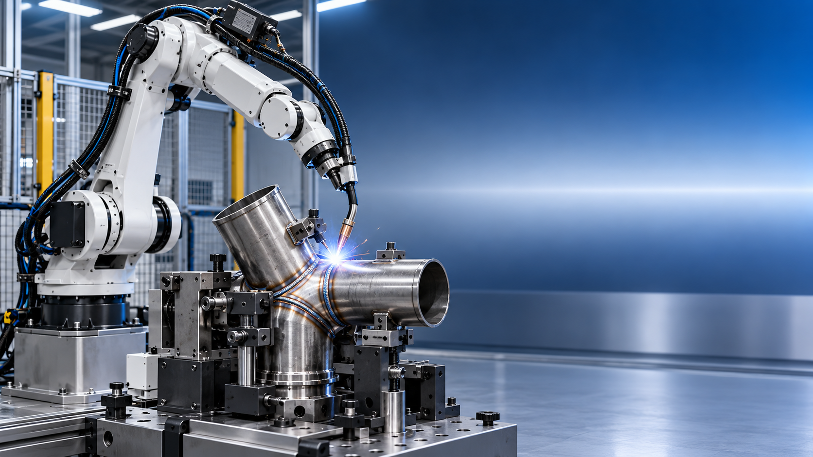
An automatic 7-axis welding robot is not defined by having “one more axis” in a generic sense. Its value lies in kinematic redundancy: the robot can reach a required torch position and orientation through more than one joint configuration. For complex welds, that redundancy can prevent abrupt wrist rotation, reduce singularity exposure, preserve a stable travel angle, and maintain clearance from fixtures or the workpiece.
That distinction matters because a robot may complete a weld path in offline simulation while still producing unstable torch angles, cable interference, limited joint access, or poor posture near the end of the seam. The relevant question is not whether seven axes are available, but whether the seventh axis creates useful alternative configurations throughout the real weld envelope.
What the seventh axis actually means
In robotic welding, “7-axis” can describe different machine architectures. A seven-joint articulated arm has a redundant internal axis, often resembling the additional freedom of a human elbow or shoulder. It can alter elbow position without materially changing the tool center point (TCP) pose. This is the configuration most directly associated with improved torch orientation in confined or spatially complex joints.
In other proposals, a conventional six-axis robot is paired with a linear track, rotary positioner, headstock-tailstock system, or another external axis. The cell may then be described as a seven-axis or multi-axis welding system. This can substantially increase reach and enable coordinated welding around cylindrical or large fabricated parts, but it is not equivalent to a seven-axis arm. The external axis changes workpiece or robot location; it does not necessarily give the wrist another way to hold the torch at the same point.
Technical evaluation should therefore begin with a kinematic definition. Required questions include:
- Is the seventh axis integrated into the robot arm, or is it an external coordinated axis?
- Can all axes move synchronously during welding, or is the external axis used only for indexing?
- Does the controller solve redundancy automatically, and can the programmer constrain preferred arm postures?
- Which axes remain available when the torch package, collision guards, dress pack, and seam-sensing hardware are fitted?
A system with a rail can be the right answer for long structural beams; a redundant seven-axis arm can be more effective for dense nodes, tubular intersections, internal corners, and assemblies where torch attitude is the limiting factor. Treating these architectures as interchangeable leads to incorrect cycle-time and accessibility assumptions.
TCP pose is only part of the welding requirement
A welding path is commonly expressed as a sequence of TCP positions with associated orientations. For a fillet weld, the torch must maintain a meaningful work angle relative to the two parent surfaces and a travel angle relative to the direction of motion. For groove welding, the required orientation is shaped by bevel geometry, root opening, access to the root, filler deposition strategy, and the need to avoid contact between nozzle and sidewall.
In a simple flat weld, a six-axis robot can often maintain these conditions without difficulty. The limitation appears when the seam curves through three-dimensional space, passes close to structural members, enters a narrow pocket, or requires transition between welding positions. At those points, the same TCP orientation may demand an impractical arm posture. A 7-axis robot can reposition its elbow or forearm while preserving the programmed TCP path.
This additional freedom is especially useful when the torch must stay within a narrow angular window. A path may be geometrically reachable, yet the torch can drift toward an unfavorable work angle if motion planning gives priority to joint travel minimization rather than process orientation. The evaluator should inspect not only the TCP trace but also the full time history of torch angle, axis values, speed, and distance to nearby geometry.
Motion continuity is more important than isolated reach
Reach studies often focus on whether the robot can access the start and finish of a seam. Welding performance depends on continuous reach between those points. A robot that reaches both ends may still encounter a wrist flip, an axis-limit condition, or a near-singularity posture in the middle of the path.
Singularities occur when two or more robot axes become kinematically aligned, reducing the robot’s ability to generate a commanded Cartesian movement without extreme joint speeds. A typical example is wrist-axis alignment during a torch rotation around the TCP. Near this condition, small changes in orientation can cause rapid motion in one or more wrist joints. The result can be reduced speed consistency, controller alarms, or unplanned reorientation.
For welding, that is not merely a robot-motion issue. A sudden configuration change can affect cable tension, torch lead position, stick-out stability, gas shielding, and collision clearance. On a critical seam, these disturbances can translate into process instability even if the robot does not stop.
Redundancy allows the controller to select another arm posture before the singularity becomes unavoidable. However, this benefit depends on path-planning settings. Some controllers optimize for shortest joint movement; others allow posture biasing, joint-limit avoidance, or user-defined arm-angle control. These functions should be demonstrated on the actual joint geometry, not inferred from a generic robot reach chart.
Torch orientation control in difficult joints
Complex joints rarely have one universally correct torch attitude. The acceptable orientation range is determined by welding process, joint design, wire diameter, shielding gas, torch geometry, bead sequence, and access conditions. The added axis does not remove these process constraints; it makes it more feasible to hold the required orientation while moving through a constrained path.
Consider a tubular branch-to-header connection. As the torch travels around the saddle-shaped intersection, the local surface normal changes continuously. The robot must modify torch orientation while preserving a consistent standoff and avoiding interference between the gas nozzle, the tube wall, and adjacent structural members. A redundant arm can often carry out that orientation change with smoother distribution of movement across the shoulder, elbow, and wrist.
Similar advantages can arise in:
- multi-plane fillet welds on frames with stiffeners, gussets, and cross-members;
- box-section corners where the torch approaches through a restricted opening;
- cast or machined components with irregular external contours;
- circumferential welds where access changes significantly around the part;
- large assemblies where fixture members obstruct a direct approach path.
There is a limit to what motion freedom can solve. If the contact tip-to-work distance is physically impossible to maintain, the nozzle cannot enter the joint, or the welding procedure requires a torch angle that conflicts with the surrounding geometry, a seventh axis cannot compensate for poor joint accessibility. In those cases, torch selection, joint redesign, fixture modification, or repositioning equipment may have a greater effect than robot kinematics.
Clearance must include the whole torch package
CAD-based reach validation frequently treats the tool as a simplified cylinder. That is insufficient for welding. The relevant collision model should include the torch neck, gas nozzle, contact tip extension, wire feeder conduit, cable bundle, anti-collision device, seam sensor, reamer access requirements, and the geometric envelope created by cable movement.
A 7-axis robot may improve clearance by moving the elbow away from the part, but an alternative posture can also move the dress pack closer to a fixture. The clearance problem is dynamic: a configuration that is safe at one waypoint may create cable sweep interference during travel to the next.
Tool-center-point calibration deserves equal attention. An added axis increases the number of joint combinations that can place the torch at the same programmed coordinates. If TCP definition, torch geometry, or flange mounting are inaccurate, deviations may appear differently across postures. A robust acceptance test should include repeated approaches to a reference feature from several robot configurations, rather than verifying TCP accuracy only in one convenient pose.
Path planning and redundancy resolution
Redundant kinematics require a policy for choosing among multiple valid solutions. Without one, the robot may make posture changes that are mathematically valid but operationally poor. A suitable motion strategy generally needs to balance several objectives: maintaining torch orientation, avoiding joint limits and singularities, preserving clearance, reducing unnecessary axis reversal, and keeping cable motion controlled.
For critical seams, it is useful to define posture boundaries rather than leaving the entire path to automatic optimization. These may include preferred elbow side, prohibited wrist rotations, restricted joint ranges, or approach and departure postures. The exact programming method differs by controller, but the principle is constant: redundancy should be governed by welding constraints, not solely by robot reachability.
Sampling density also matters. If orientation points are too sparse along a rapidly changing seam, interpolation can produce unintended intermediate postures. Conversely, excessive point density can make editing difficult and may introduce small speed changes where blending is not configured correctly. The best representation depends on the controller’s spline, circular, and linear interpolation capabilities, as well as the accuracy of the workpiece model.
Workpiece variation can consume the available motion margin
A simulated path normally assumes nominal part geometry and repeatable fixturing. Real weldments introduce fit-up gaps, tack-weld distortion, material variation, and loading-position error. When a planned torch path already uses most of the available clearance or approaches an axis limit, even modest variation can make the cell unreliable.
Seam tracking, through arc sensing, laser sensing, or other methods, can correct path position in certain applications. It does not automatically solve robot posture selection. A sensor may move the TCP to follow an actual seam while the robot’s joints approach a limit or the nozzle moves closer to an obstruction. Motion planning and seam-tracking logic need to be assessed together.
This is particularly important where the part is large relative to the robot’s working envelope. A seven-axis arm may create enough margin to absorb normal positional variation. But where the variation is dominated by weak fixturing or significant component distortion, the primary corrective action remains fixture and process control, not a more complex robot.
Cell design can be more decisive than arm-axis count
Robot selection should not be separated from fixture design, part presentation, torch choice, and weld sequencing. Rotating the workpiece into a more favorable position can simplify orientation control and improve weld pool behavior. For circular or long components, a coordinated positioner may offer greater process value than an internally redundant arm because it keeps the weld in a preferred gravity position.
For example, a fabrication line may combine robotic welding with thread-forming operations for related fastener components. The Z28-150 thread rolling machine is designed for cold-forming external threads rather than welding, but it illustrates why cell boundaries need to be defined precisely: a thread-rolling machine’s part range, loading method, and production rhythm should not be assumed compatible with a welding robot simply because both serve metal-component production. Material flow, guarding, inspection points, and handling interfaces require separate engineering.
That distinction also applies within the welding cell. An automatic 7 axis welding robot may justify its added control complexity when fixture redesign is constrained by product geometry or part-family variation. If fixtures can instead expose the weld in a simple posture, a conventional six-axis robot with suitable positioning equipment may be easier to validate and maintain.
Performance evidence that should be requested
Manufacturer specifications provide payload, reach, repeatability, and axis ranges, but these values do not establish welding suitability for a particular joint. ISO 9283 provides a recognized framework for evaluating industrial robot performance characteristics, including pose accuracy and repeatability under defined test conditions. Those values are useful baseline information, but they should not be confused with weld-path accuracy on a loaded production tool.
Validation should use the intended torch, cable package, workpiece fixture, and representative seam conditions. The evidence should address:
- continuous travel through the complete seam, including starts, stops, corners, and transitions;
- joint-limit and singularity margin at normal programmed speed;
- minimum clearance for torch, cable bundle, and anti-collision equipment;
- actual torch work angle, travel angle, and stick-out over the path;
- axis-speed behavior where surface orientation changes rapidly;
- repeatability after tool changes, collision recovery, and routine maintenance activities.
Weld acceptance remains governed by the applicable fabrication specification and welding procedure requirements. Depending on the work and contractual framework, relevant references may include ISO 3834 for quality requirements in fusion welding, ISO 15614 for welding procedure qualification, ISO 14732 for welding personnel and operator qualification, and ISO 5817 for quality levels of imperfections in fusion-welded joints. These standards address different parts of welding quality management; none should be used as a blanket statement that a robot configuration is suitable.
Safety and integration considerations
More degrees of freedom can create less predictable swept volumes for those accustomed to fixed six-axis postures. Safeguarding must therefore be based on the actual robot envelope, external axes, workpiece motion, automatic torch cleaning, wire cutting, and part-handling movements. ISO 10218 establishes core safety requirements for industrial robots and robot systems; the installed cell still requires a task-specific risk assessment, safeguarding design, and validation under the applicable local regulatory regime.
Recovery behavior is often overlooked. After an arc fault, wire collision, or protective stop, the robot may need to retreat from a confined joint. A posture that is collision-free during forward welding may not provide a safe reverse path if cable routing or nearby fixtures are not considered. Recovery positions, manual jog access, and restart logic should be included in the engineering review.
The strongest application for an automatic 7-axis welding robot is not simply a part that is “hard to reach.” It is a joint where stable torch orientation, uninterrupted path motion, and collision margin cannot be maintained reliably by a six-axis configuration within the available fixture and process constraints. When that condition is demonstrated through full-path simulation and representative welding trials, the additional axis becomes a measurable motion-control resource rather than an attractive but unused specification.
search
Products Navigation
Send Us A Message