




Planning an Automatic 9-Axis Welding Cell for Multi-Angle Parts
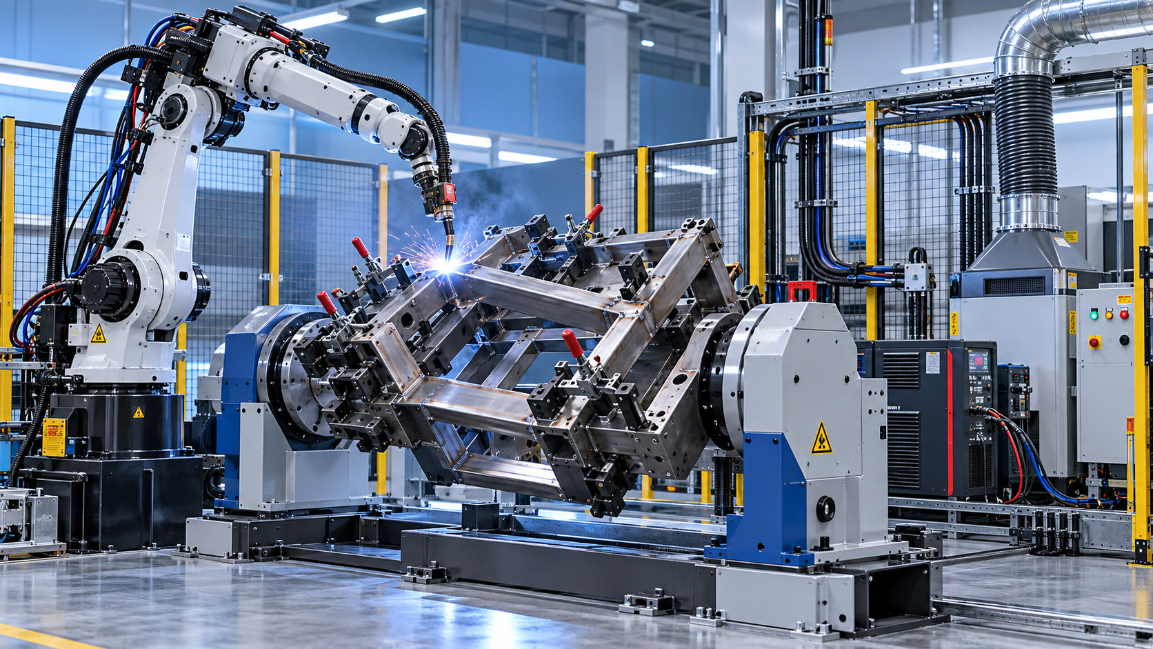
An automatic 9-axis welding robot cell is justified when the part has welds on several faces, changing joint angles, or features that are difficult to reach from one fixed position. The extra axes are not valuable simply because the cell has a higher axis count. They are valuable when coordinated robot motion and part rotation let the torch maintain a stable working angle, travel direction, and wire position without repeated manual handling.
That distinction should drive the plan. A cell that can theoretically reach every seam may still perform poorly if the fixture allows distortion, the positioner rotates through awkward orientations, or the operator must stop the system too often to change tooling. For multi-angle parts, the most reliable approach begins with the component and its weld requirements, then builds the robot, external axes, tooling, and material flow around them.
Define the part family before selecting the cell
“Multi-angle part” covers very different manufacturing problems. A welded frame with four similar corners, a fabricated housing with internal seams, and a structural assembly with long diagonal joints may all need position changes, but they do not need the same automation strategy.
Start with a representative family of parts rather than the most difficult single component. Gather the drawings, 3D models, material grades, thickness ranges, joint types, weld lengths, tolerances, and expected production mix. Include the variations that production expects to run during the life of the cell, not only the first part number.
A useful early question is: which welds require the workpiece to move, and which can be reached by changing robot posture alone? A conventional six-axis robot may cover several angled seams if the fixture presents the part well. A 9-axis arrangement usually becomes more appropriate when external positioners must rotate or tilt the part while the robot tracks the joint. The added coordinated motion can keep welds closer to a favorable position, reduce torch access compromises, and avoid excessive robot wrist rotation.
Do not assume that every seam should be welded in a flat position. Some assemblies cannot be reoriented without clearance conflicts, risk of part movement, or excessive fixture complexity. The planning objective is to create a repeatable set of practical welding positions, not to force an idealized orientation for every millimeter of weld.
Separate robot axes from workpiece-positioning axes
An automatic 9-axis welding robot commonly combines a six-axis robot with a three-axis external system, although the exact arrangement varies. The external axes may include a turntable, headstock-tailstock positioner, tilt-and-rotate unit, linear track, or another coordinated device. Their role is to present the joint consistently while the robot maintains torch geometry.
For multi-angle fabrications, a two-axis positioner often supplies rotation and tilt. A third external axis may be a robot travel track, a positioner lift, or an additional rotary function. The correct configuration depends on the part’s envelope, weight distribution, weld access, and loading method. It should not be selected from axis count alone.
Pay close attention to the difference between reach and process access. Reach means the robot can physically put the torch near the seam. Process access means the torch can hold the required work angle, travel angle, contact-tip distance, and gas coverage while avoiding clamps, tack welds, and surrounding geometry. The latter determines weld quality.
Fixture design is the foundation of repeatable robotic welding
Robots repeat positions accurately; they do not correct inconsistent incoming assemblies by themselves. If parts are placed differently from cycle to cycle, a taught path may run beside the joint, strike a clamp, or produce variable bead placement. For this reason, fixture design should be treated as a core part of the automatic welding cell, not as a separate afterthought.
A fixture needs clear datum logic. Locate the part from features that are stable in the upstream process and meaningful to the weld geometry. Avoid locating from thin edges, flexible flanges, or surfaces that change after bending and tack welding unless the process is designed around those variations. Three-dimensional locating based on primary, secondary, and tertiary references helps prevent the part from shifting in multiple directions.
Clamps must hold the assembly against welding forces and rotational motion without distorting it. Pneumatic, hydraulic, or manual clamps can all be appropriate, but every clamp creates a possible access conflict. In practice, the most difficult fixture problem is often not holding the part; it is holding it while leaving enough access for the torch, wire feeder, reamer path, and positioner rotation.
Consider thermal distortion before committing to hard tooling. Long seams, thin material, uneven joint gaps, and asymmetric weld sequences can pull an assembly away from its intended geometry. A robust cell may need staged welding, alternating seam order, support points near flexible areas, or separate stations for tacking and final welding. The fixture should allow inspection and adjustment of wear components, locators, and clamp surfaces because these conditions gradually influence part position.
Use reach analysis to expose problems before fabrication
Cell simulation is most useful when it answers production questions, not when it merely produces an attractive robot animation. The model should include the actual torch body, neck, wire feeder path, fixtures, clamps, safety fencing, positioner, part variants, and expected load/unload zones. Simplified models can conceal the exact collisions that cause commissioning delays.
Review every seam for approach, welding, retract, and positioner movement. A torch may clear the part while welding but collide while approaching the start point. The robot may reach a seam at one positioner angle but encounter a wrist singularity as it follows the path. A long torch neck may improve access to a corner while reducing stiffness and increasing collision exposure elsewhere.
Joint tracking requirements also need an early decision. When part fit-up is tightly controlled and the fixture provides repeatable location, offline programming or taught points may be sufficient. When incoming parts have variable gaps, dimensional variation, or seams that shift after tacking, seam finding, touch sensing, or arc-based tracking may be needed. These tools improve tolerance to variation, but they are not substitutes for sound part preparation and fixture control.
Plan the welding package as part of the motion system
The torch, power source, wire delivery, torch cleaning, and cable routing affect whether the system can operate continuously. A multi-axis cell may repeatedly rotate the workpiece through positions that twist cables, restrict wire feeding, or bring hoses too close to hot metal. Dress packs need defined movement paths and protection from spatter, sharp edges, and pinch points.
Specify access for consumable changes and torch cleaning. A reamer or cleaning station must be placed where the robot can reach it without interrupting safe loading activity. If the process uses different wire types or shielding gases across the product mix, calculate the changeover procedure before assuming the cell can run all variants unattended.
Balance cycle time against the complete production flow
A quoted robotic cycle time is only one element of capacity. The practical cycle includes loading, part verification, clamping, robot travel, welding, positioner rotation, cleaning, unloading, and planned recovery from normal faults. A cell that saves seconds during arc-on welding can lose its advantage if the operator spends too long changing fixtures or removing parts from an inconvenient position.
For higher volume work, a dual-station arrangement can allow loading on one side while welding takes place on the other. This can reduce waiting time, but it also adds floor space, safety interlocking, fixture cost, and process coordination. For lower-volume or frequently changing parts, a single-station cell with modular fixtures may provide a better balance between automation and flexibility.
Part flow upstream matters as much as the welding enclosure. Bent, cut, machined, or rolled components must arrive in a condition the fixture can locate. If the assembly includes threaded fasteners or threaded structural features, the forming route should also be considered early. For example, a Z28-500 thread rolling machine may be relevant where high-strength external threads, anchor bolts, or larger-pitch threaded components are produced before fabrication. The welding cell still needs protection against weld spatter and heat exposure around those features, so thread formation and welding sequence should be coordinated rather than planned as isolated operations.
Safety and access must be designed into the layout
Robotic welding requires more than fencing around a robot. The safety concept must account for the motion of the robot and the rotating workpiece, hot surfaces, arc radiation, fumes, spatter, stored energy in clamps, and safe operator access during loading and fault recovery.
Determine early where operators stand, where parts are presented, how completed assemblies are removed, and how they enter the cell for consumable replacement or fixture adjustment. A layout that gives clear access during normal operation but forces awkward entry during recovery will lose time and encourage unsafe workarounds.
Interlocks should prevent positioner rotation while the loading area is accessible. The design should also make the status of clamps, part presence, and safe robot position understandable from the operator interface. Recovery procedures deserve special attention: after a wire feed fault, collision stop, or incomplete cycle, the operator should be able to identify the cell state and return it to a safe sequence without guessing.
Commissioning should prove the process, not just the program
Before site acceptance, define what the cell must demonstrate. This normally includes the part variants to be run, visual weld acceptance requirements, critical dimensions after welding, cycle sequence, fixture repeatability, and expected response to common interruptions. A successful dry run is not enough; the cell must produce representative parts repeatedly under normal loading conditions.
Begin with stable parts and a limited weld procedure set. Once the basic motion, clamping, and weld results are consistent, introduce the more difficult variants. Changing robot paths, fixture locations, welding parameters, and part design at the same time makes root-cause analysis slow and unreliable.
Document programs, fixture settings, consumables, reference points, and backup routines before production ramps up. An automatic welding cell becomes easier to maintain when technicians can distinguish a part-location issue from a torch condition issue, a weld-parameter issue, or a robot-path issue.
A practical sequence for moving the project forward
- Classify the planned part family by size, weight, joint geometry, material thickness, and production volume.
- Identify seams that demand part rotation, tilt, continuous coordinated movement, or special torch access.
- Create fixture datums and clamp concepts before finalizing robot and positioner selection.
- Run a detailed reach and collision study using realistic tooling and all required part variants.
- Define the full operating cycle, including loading, cleaning, changeovers, inspection, and fault recovery.
- Set weld quality and acceptance criteria that can be verified during commissioning and normal production.
- Release the cell layout only after safety access, utility routing, fume extraction, and material flow have been resolved.
The strongest automatic 9-axis welding robot plan is one in which each axis has a defined job: presenting the part, improving torch access, maintaining a usable welding orientation, or keeping the cell productive through a practical loading sequence. When an axis does not solve one of those problems, it may add complexity without improving the result. Starting from fixture stability and seam access produces a cell that is easier to commission, simpler to operate, and better prepared for changes in the part mix.
search
Products Navigation
Send Us A Message