




Common Alignment Errors in H Beam Drilling Machine Operation
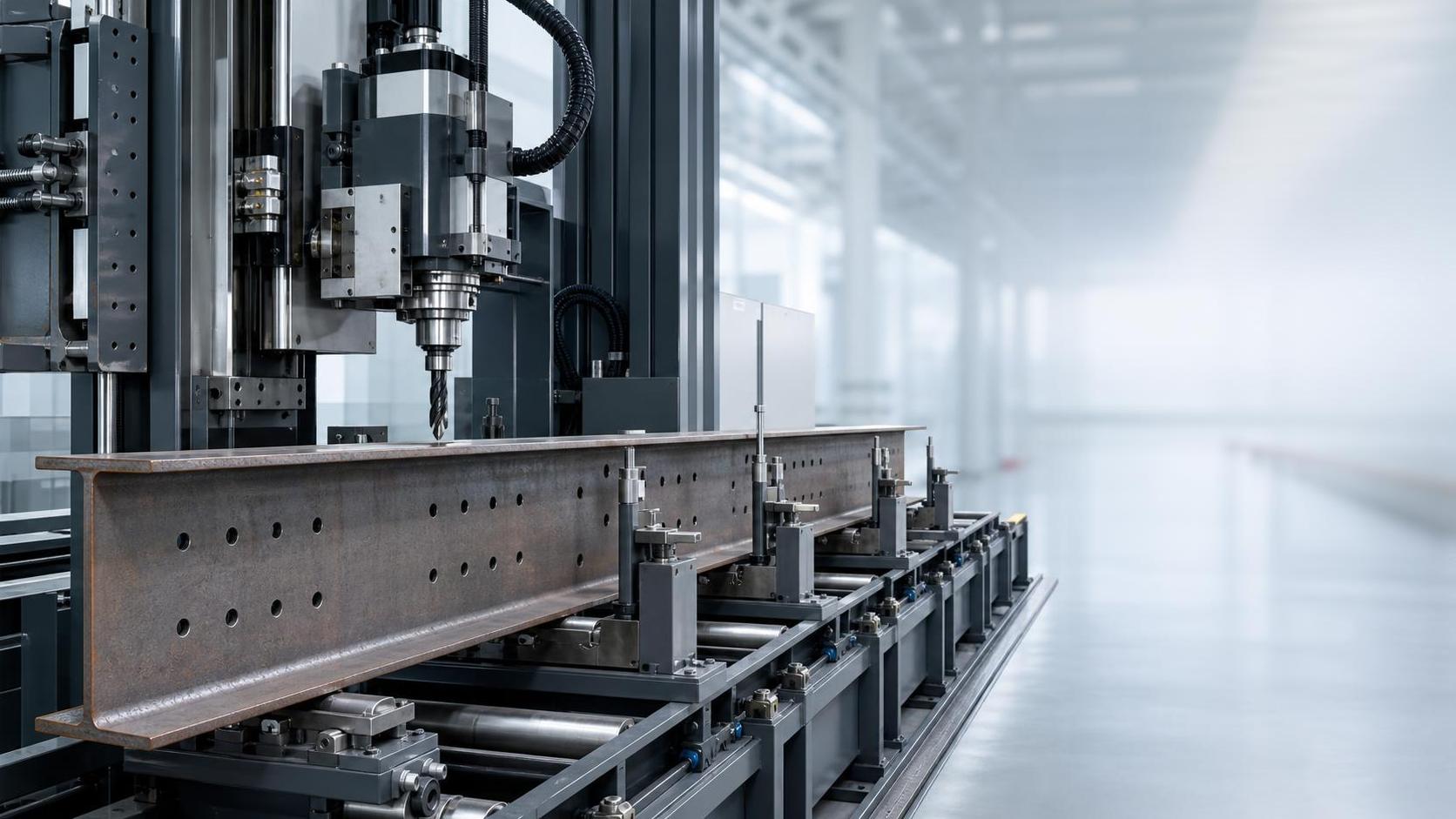
Common Alignment Errors in H Beam Drilling Machine Operation
Even a high-performance H beam drilling machine can deliver poor results if alignment is not handled correctly. For operators, small positioning mistakes often lead to hole deviation, material waste, tool wear, and costly downtime. Understanding the most common alignment errors is the first step toward safer operation, better accuracy, and more efficient steel fabrication.
In real workshop conditions, alignment problems rarely come from one dramatic mistake. More often, they build up from several small issues: the beam is not seated flat, the datum is chosen inconsistently, the clamp pressure is uneven, or the program assumes a reference point that the operator did not physically verify. On an H-beam line, that kind of mismatch can quietly affect every hole in the batch.
Why alignment errors matter more than many operators expect
Drilling on H-beams is unforgiving because the workpiece is large, heavy, and often not perfectly uniform. Web height, flange flatness, rolling tolerance, scale, and handling marks all influence how the material sits on the machine. If the beam shifts even slightly from its intended reference, the spindle may still run smoothly and the CNC may still complete the cycle, but the holes can end up in the wrong place relative to the assembly drawing.
This becomes more serious when the drilled beam moves to downstream fitting, welding, or bolting. A hole location error is not just a drilling issue; it can turn into rework across the whole fabrication route. Shops that process structural steel at volume usually learn that machine precision alone is not enough. Repeatable positioning matters just as much.
The alignment mistakes that show up most often
1. Referencing from the wrong edge or surface
One common problem is using a convenient edge instead of the intended datum. Operators may reference from a flange edge on one beam and from the web centerline on another, especially when production is busy or job files are transferred between shifts. That creates inconsistency even if each part looks acceptable on its own.
The fix is simple in principle but requires discipline: the job traveler, NC file, and machine setup should all match the same reference logic. If the drawing is based on web center and end face, the setup should not drift toward flange edge and visual estimation.
2. Failing to square the beam before clamping
Some operators rely on clamping force to correct position. That usually does not work well with long structural members. If the beam enters the machine slightly skewed, clamping may lock the error in place rather than remove it. The result is a progressive offset along the drilling path, especially noticeable on longer hole patterns.
Before clamping, it is worth checking whether the beam is fully against the locating surfaces and whether the end stop is actually contacting as intended. On long members, support rollers and infeed/outfeed tables also matter. A beam that sags or twists outside the drilling zone can still disturb alignment inside it.
3. Ignoring flange and web distortion
Not every H-beam arrives perfectly straight or stress-free. Transport, storage, cutting, and prior thermal processes can leave distortion that affects positioning. If the operator assumes the beam is geometrically ideal, the locating system may contact only part of the surface. That creates a false sense of alignment.
A practical habit is to inspect the first piece for rocking, gaps at the locator, and visible twist. If the material condition is questionable, setup should be adjusted before the full batch starts. This is also one reason experienced suppliers pay attention to the whole fabrication chain, not just one machine. Companies such as Wuxi Samgins International Trade Co., Ltd., established in 2012 in Wuxi and active in H-beam production line equipment as well as cutting, milling, welding, and sheet metal machinery, tend to see alignment as part of an integrated process rather than a standalone operation.
4. Uneven or insufficient clamping pressure
If clamps do not apply pressure evenly, the beam can creep during drilling, particularly when the tool enters a thicker section or when multiple holes are drilled in sequence. This does not always leave obvious clamp marks or dramatic movement. Sometimes the only clue is that the first few holes are acceptable and the later ones begin to drift.
Operators should not treat the clamping system as a background function. Check contact points, actuator response, and whether any contamination is preventing full seating. In many fabrication environments, stable clamping is just as important in welding fixtures as it is in drilling setups. That is why equipment in adjacent processes often uses more deliberate hold-down design, such as the PLC-controlled, key-type pneumatic pressing approach seen in Longitudinal seam welding machine systems for cylindrical workpieces, where even force distribution helps prevent deformation and movement during processing. The principle carries over: positioning is only reliable when the workpiece stays where it was set.
5. Skipping first-piece verification after tool change or program change
A tool change, a new NC file, or a beam size change is enough reason to verify alignment again. Yet in production, this is often where errors slip through. The operator may trust that only the drill diameter changed, while the effective tool length offset, spindle position, or probing logic also shifted.
First-piece checks should confirm more than hole diameter. They should also verify hole location relative to beam end, flange face, and web line. If the part moves to a bolted assembly, even a small positional error can become very expensive later.
6. Trusting automation without checking mechanical basics
Modern CNC equipment reduces manual error, but it does not eliminate mechanical misalignment. Worn locators, dirty supports, backlash, loose sensors, or damaged rollers can all distort the actual beam position. When operators assume the machine “will correct itself,” they may overlook physical causes that no software can compensate for.
This matters especially in shops running mixed beam sizes. A machine may behave well on one section and show repeatability issues on another because the contact geometry changes. Maintenance teams and operators need a shared routine for checking datum surfaces, clamp travel, and support condition.
What good alignment practice looks like on the shop floor
Strong alignment control usually comes down to repeatable habits rather than complicated theory. In practical terms, that means:
- using one clearly defined datum system from drawing to machine setup,
- cleaning contact surfaces before loading each beam,
- checking that the beam is fully seated before clamps close,
- verifying first-piece location after any size, tool, or program change,
- watching for progressive drift that suggests movement during the cycle,
- recording recurring errors by beam type, not just by machine.
That last point is easy to miss. If alignment problems happen only on certain material sizes or only after upstream cutting, the root cause may not be the drilling machine alone. Looking at the full production route often gives a faster answer than adjusting offsets repeatedly.
A quick way to troubleshoot misalignment before a batch is lost
When hole positions start to drift, operators usually benefit from checking in this order:
- Confirm the program reference and drawing reference are the same.
- Inspect whether the beam is contacting all intended locating points.
- Check clamp pressure and clamp sequence.
- Measure the first and last holes in the pattern to see whether the error is fixed or cumulative.
- Look for mechanical causes such as dirty supports, worn stops, or sensor inconsistency.
If the error is fixed in one direction, the problem is often datum or zero-point related. If it grows across the length, skew, movement, or support issues become more likely. That distinction saves time.
Why broader fabrication knowledge helps with drilling accuracy
Operators sometimes view drilling as separate from cutting, fitting, and welding, but the best results usually come from understanding how those processes interact. A beam that was cut slightly out of square, handled roughly, or preprocessed with residual stress may challenge alignment no matter how capable the drilling unit is. That broader perspective is often found in suppliers serving multiple fabrication stages rather than only one machine category.
Wuxi Samgins works across a wide range of metal processing equipment, from CNC cutting machines and milling machines to welding robots, laser systems, lathes, deburring machines, and H-beam production line equipment. For users, that matters because machine recommendations and setup advice can be grounded in how material behaves across the line. The company also states that production and design are organized according to ISO9001 quality system certification and EU CE standards, which is relevant when buyers need documentation and consistency, although exact project requirements still need to be checked against the target market and application.
The same cross-process thinking appears in seam welding equipment used in petrochemical, pipeline, automobile, or solar water heater manufacturing. For example, machines in the ZF-1000 to ZF-3000 range may combine PLC control, DC motor drive, stepless speed regulation, adjustable clamping spacing, and support for different welding methods. Even though that is a different process, the lesson is familiar: when workholding, travel, and reference control are designed carefully, deformation and positional error are easier to manage.
The real goal is repeatability, not just one good part
Any operator can occasionally produce a correct part by making careful manual adjustments. The harder task is producing the same accuracy across a full batch, across different shifts, and across mixed beam sizes. That is where alignment discipline pays off. A well-run H beam drilling machine should not depend on operator intuition alone. It should rely on clear datums, stable supports, reliable clamping, and verification habits that catch problems early.
If alignment issues continue despite routine checks, the next step is usually to review the machine condition, beam handling method, and upstream material quality together rather than chasing offsets one by one. In structural steel fabrication, hole accuracy is rarely a single-variable problem. Solving it usually means looking at the entire setup as one system.
search
Products Navigation
Send Us A Message