




Common Welding Robot Integration Problems and How to Fix Them on Production Lines
Why Welding Robot Integration Problems Show Up on Real Production Lines
A Welding robot can raise output fast, but integration problems rarely start at the robot alone.
They usually appear where motion control, fixtures, welding power, sensing, and line logic must work together under production pressure.
In machining and fabrication lines, that difference matters.
A bench test may look stable, while the same Welding robot begins missing starts, drifting off seam, or pausing on interlocks after installation.
The practical question is not whether faults happen.
It is which production conditions make them more likely, and which fixes actually hold during repeated shifts.
This is especially relevant for companies handling mixed metal fabrication, long structural parts, and automated welding cells across different export standards.
With broad equipment experience in welding, cutting, forming, and CNC systems, Wuxi Samgins International Trade Co.,Ltd works in exactly these practical line conditions.
That background matters because Welding robot integration is rarely isolated from upstream cutting accuracy or downstream handling rhythm.
Actual Line Conditions Change the Root Cause
Different production lines create different failure patterns, even when they use similar robot brands.
Small batch cells often struggle with changeover consistency.
Heavy structural welding lines more often face rail alignment, thermal distortion, and long travel coordination.
Parts with tight cosmetic requirements push attention toward arc stability, spatter control, and torch angle repeatability.
By contrast, thick section work usually exposes fixture rigidity, grounding quality, and heat input management first.
A useful way to judge any Welding robot issue is to separate four layers.
- Control layer: PLC, fieldbus, I/O mapping, and program handshakes.
- Mechanical layer: base rigidity, rail straightness, fixture wear, and backlash.
- Process layer: wire feed, shielding gas, welding parameters, and seam variation.
- Safety layer: interlocks, emergency stops, grounding, and guarded access logic.
When teams skip that separation, they often tune parameters for what is really a mechanical or communication problem.
When Communication Faults Stop the Cell More Than Welding Defects
On busy lines, communication faults often look random.
The robot may lose ready signals, fail to release a clamp, or wait forever for weld completion feedback.
In practice, these stoppages usually come from inconsistent fieldbus mapping, cable interference, loose connectors, or sequence timing that was only tested at low speed.
This is common where the Welding robot is added to an older fabrication line rather than designed into a new one.
The fix starts with signal tracing, not parameter guessing.
Check whether every handshake has a clear source, timeout, and fail state.
Then verify cable routing near welding power lines, because electrical noise often appears only during arc start or heavy movement.
A stable Welding robot cell usually has documented I/O logic, shielded communication lines, and event logs tied to exact stop codes.
Positioning Errors Usually Start Outside the Robot Body
When weld seams drift, the first reaction is often to reteach points.
That helps briefly, but it does not solve recurring offset.
In real production, positioning problems more often come from fixture repeatability, rail installation error, part size variation, or thermal distortion after the first passes.
This is more visible on long beams, frames, and fabricated assemblies.
Where travel distance is large, a small base error becomes a meaningful seam deviation.
For those conditions, a gantry layout with servo carriage movement can be easier to stabilize than repeated manual workaround.
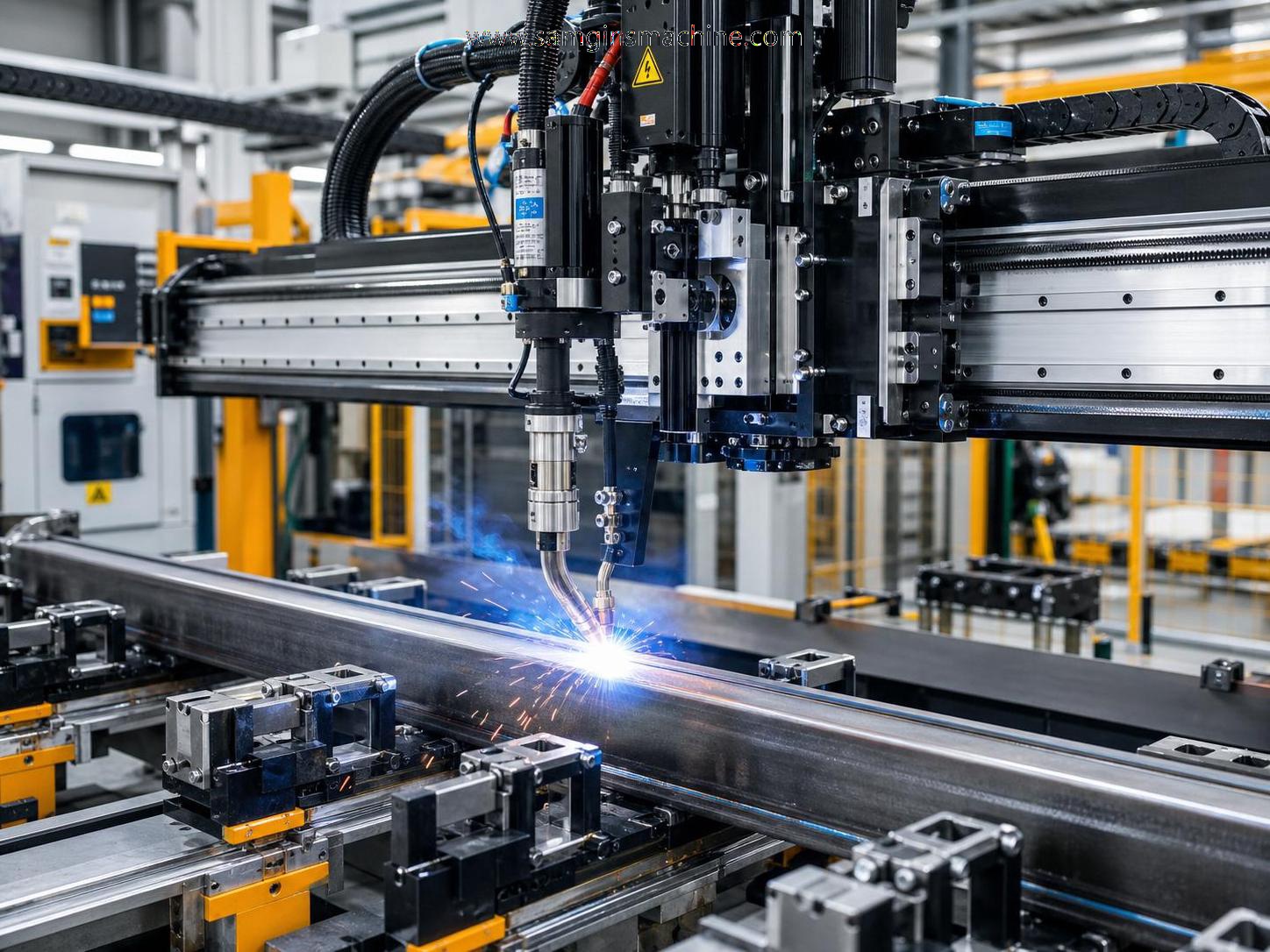
One example is the 9 axis gantry type welding robot, built around a dedicated rail, slide carriage, robot system, welding power supply, and torch cleaning station.
Its automatic arc tracking is useful where seam correction must happen during motion, not after defects appear.
The key judgment is simple.
If error grows with travel length, check rail geometry and carriage repeatability first.
If error changes by batch, inspect incoming part tolerance and fixture wear.
Weld Quality Problems Depend on Part Mix and Process Stability
Not every unstable weld comes from bad programming.
A Welding robot can repeat the wrong process very accurately.
On lines producing similar parts all day, poor weld appearance often points to torch contamination, wire feed fluctuation, gas flow issues, or grounding resistance.
On mixed production lines, the bigger issue is usually parameter mismatch between different joint types and material thicknesses.
That is why one-key weld extraction and manual parameter matching can be more practical than relying on one default recipe.
A short comparison helps clarify where to look first.
Safety Interlock Issues Often Reveal Poor Integration Discipline
Safety faults are sometimes treated as nuisance stops.
That is a costly mistake.
A Welding robot line with unstable interlocks usually has deeper integration gaps around access control, grounding, or emergency stop zoning.
This becomes more sensitive on export projects, where line acceptance must align with ISO9001-managed production and CE-oriented design practice.
Well-integrated cells use clearly grouped emergency stops, reliable safety grounding, and visible machine states.
Indicator lights showing red for fault, yellow for pause, and green for running are simple, but they reduce diagnosis time on large lines.
The real test is whether the Welding robot stops safely without creating confusing restart conditions.
A fast restart is useful only when the stop reason is fully known.
Different Production Scenarios Need Different Fix Priorities
The same fault code does not always justify the same response.
What matters is how the Welding robot is being used on that line.
- For compact cells, prioritize fixture repeatability and quick recipe verification during changeover.
- For H-beam or long workpiece lines, prioritize travel accuracy, seam tracking, and multi-zone coordination.
- For heavy section welding, prioritize heat distortion control, grounding path quality, and torch service intervals.
- For export-oriented lines, prioritize safety documentation, standard compliance, and spare part consistency.
For workpieces beyond 12 meters and under 25 meters, zone-based welding with two robots can reduce cycle bottlenecks significantly.
That approach is often more effective than pushing one Welding robot to cover excessive travel with frequent repositioning.
Where Misjudgment Happens Before the First Repair Attempt
Some integration problems last too long because the initial judgment is wrong.
Several patterns show up repeatedly.
- Looking only at robot specifications, while ignoring fixture wear and part tolerance variation.
- Focusing on purchase cost, while underestimating maintenance access and downtime impact.
- Treating similar weldments as identical, even though joint access and distortion behavior differ.
- Retuning weld parameters before checking cable shielding, grounding, and torch condition.
- Assuming safety stops are operator issues, when logic zoning is actually inconsistent.
The more complex the production line, the more expensive these misjudgments become.
A Practical Next Step Before Changing Hardware
Before replacing major components, map the fault to the exact production scenario.
Record when the Welding robot fails, which part family is running, what travel distance is involved, and whether the fault appears during arc start, motion, or restart.
Then compare three things side by side.
Check the line logic, the mechanical reference condition, and the weld process window.
That usually reveals whether the problem needs tuning, reinstallation, fixture correction, or a more suitable long-travel setup.
Where large fabricated parts, rail travel, and real-time seam correction are central, reviewing options such as the 9 axis gantry type welding robot can help frame the right integration standard.
The most reliable Welding robot result usually comes from matching the equipment architecture to the line condition, not from forcing one configuration into every job.
search
Products Navigation
Send Us A Message