




Do H beam 3D drilling machines require separate jigging for tapered flanges or handle them natively?
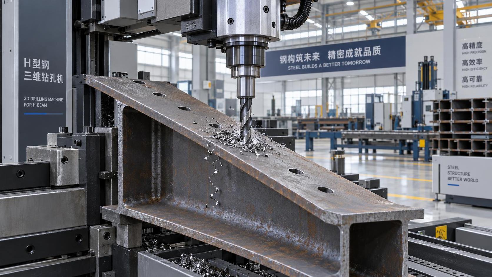
Do H-beam 3D drilling machines require separate jigging for tapered flanges—or handle them natively?
If you’re operating an H-beam fabrication line—or specifying equipment for one—you’ve likely run into this question during layout planning or pre-production review: “Do I need custom jigs every time I drill a tapered flange?” The short answer is no—not with modern, purpose-built H-beam 3D drilling machines. But the real answer depends on how deeply the machine’s control architecture and mechanical design integrate geometry-aware motion.
Tapered flanges aren’t rare outliers. They appear in crane rails, portal frames, and seismic bracing where variable moment resistance demands thicker flanges at supports and thinner ones mid-span. Drilling holes on those tapers—especially for high-strength bolts or connection plates—requires consistent perpendicularity to the local flange surface, not just alignment to the beam’s global coordinate system. That’s where many older or generic CNC drilling systems hit a wall.
Legacy setups often rely on manual fixture adjustment or dedicated tapered-jig sets. Each new taper angle means repositioning clamps, verifying angular offsets, recalibrating probe points—and risking cumulative error across multiple holes. In high-mix shops, that eats setup time, increases operator dependency, and introduces inconsistency between shifts. Worse, it makes automated TEKLA-to-machine workflows brittle: if your model includes a 5° taper but your jig assumes 0°, the hole pattern drifts.
Native taper handling isn’t about marketing—it’s about axis architecture
True native taper support comes from machines built with coordinated multi-axis kinematics—not bolt-on software patches. Think of it like this: a standard 3-axis drill head moves X/Y/Z. A tapered-flange-capable system adds real-time tilt compensation—either via a rotating tool spindle (C-axis), a tilting drill carriage (B-axis), or both—controlled by the same motion planner that interprets the beam’s actual cross-section geometry.
This isn’t just “tilt the drill.” It’s synchronizing the tilt angle with the exact X-position along the flange edge, compensating for web curvature, and maintaining feed rate consistency as the drill enters at varying angles. That level of coordination only works when the machine’s firmware reads the full 3D profile—not just nominal dimensions—and adjusts trajectory on-the-fly. Machines certified to ISO 9001 and EU CE standards, like those supplied by Wuxi Samgins, embed this logic directly into their motion controllers—not as an optional module, but as baseline behavior.
Where things go sideways: assumptions vs. reality
Some buyers assume “3D drilling” automatically equals taper-ready. It doesn’t. Many entry-level systems label themselves “3D” because they move in three linear axes—but lack rotational degrees of freedom needed for angled drilling. Others offer tilt capability but restrict it to preset angles (e.g., 0°, ±5°, ±10°), forcing operators to map taper zones manually and switch modes mid-job. That defeats the purpose of automation.
Also watch for “simulated taper handling”: software that rotates the entire part coordinate system before drilling. This works only if the taper is uniform and perfectly aligned with the beam’s longitudinal axis—and fails completely on rolled sections or beams with compound tapers. Real-world fabrication rarely delivers perfect geometry.
What actually matters on the shop floor
Two practical checks matter more than spec sheet claims:
- Can it drill a continuous taper without stopping? Try a test piece with a 0°–8° linear taper over 2 meters. If the machine pauses, re-homes, or requires manual intervention at transition points, it’s not truly native.
- Does it accept direct TEKLA or SDS/2 geometry export—including flange thickness gradients? If you must flatten taper data into discrete segments or override angles in post-processor, you’re adding failure points.
Wuxi Samgins’ approach reflects years of field feedback: their H-beam 3D drilling solutions treat taper as intrinsic to the part model—not an exception to be worked around. That’s why their ISO 9001-certified systems ship with integrated laser profiling and adaptive spindle tilt, verified during factory acceptance testing using calibrated taper gauges—not theoretical benchmarks.
A note on workflow integration
Native taper handling pays off most when combined with broader automation—like robotic welding cells that share the same geometric reference frame. For example, the BR-2010A Pro/XB12-A8DP MAX Eight-Axle Cantilever Dual-Motor uses laser positioning and automatic task allocation to align welding paths with drilled hole locations—even on tapered flanges. There’s no separate “taper jig” for welding either. The system reads the same TEKLA file, applies the same geometric compensation, and executes both drilling and welding in a single, coherent sequence.
That tight coupling eliminates the “translation gap” between drilling and downstream processes—a gap where misalignment, rework, and fit-up delays quietly accumulate. In steel fabrication shops running mixed batches of structural, architectural, and seismic components, that consistency saves hours per week—not just in setup, but in verification and rework.
Bottom line: don’t buy “3D”—buy “geometry-aware”
When you sell H beam 3D drilling machine solutions—or operate one—don’t settle for “it can do tapers.” Ask how it does them. Does it require jig changes? Does it interpolate smoothly across variable angles? Does it maintain positional repeatability within ±0.15 mm across the full flange width? And critically: does it pass that accuracy forward to welding, assembly, or inspection?
The machines that answer “yes” to all four aren’t just faster—they reduce reliance on skilled setup personnel, shrink first-article approval cycles, and make high-mix, low-volume production economically viable. That’s not a feature. It’s the difference between automating a step and automating a process.
For fabricators in Southeast Asia, Europe, or North America who ship to strict code requirements—whether ASCE 7, Eurocode 3, or GB 50017—the ability to drill tapered flanges natively isn’t convenience. It’s compliance infrastructure.
search
Products Navigation
Send Us A Message