




Why space frame welding machine factory layouts impact cycle time more than robot speed alone
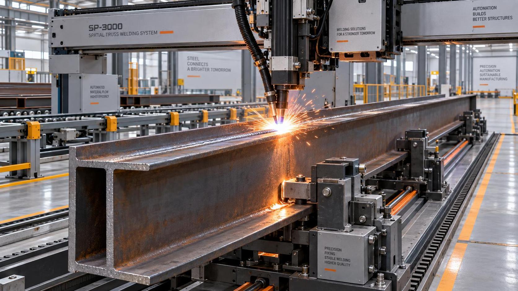
When a manufacturing decision-maker evaluates a new space frame welding machine factory, the first instinct is often to compare robot speeds: 1.2 m/min vs. 1.5 m/min, arc-on time, or repeatability specs. But in real-world structural welding operations—especially for large-scale, high-tolerance components like bridge girders, ship frames, or high-speed rail supports—the layout of the entire factory floor isn’t just background context. It’s the primary determinant of cycle time. Not secondarily. Not incrementally. Decisively.
Why “robot speed” alone is a misleading metric
Robot speed—measured in travel or weld feed rate—is only one variable in a tightly coupled chain: material arrival → positioning → clamping → seam tracking → welding → flux recovery → part removal → next part loading. If any link slows or stalls, the fastest robot sits idle. Worse: it creates queuing, operator intervention, and rework. In our field experience supporting structural fabricators across Southeast Asia, Europe, and the Americas, we’ve seen cases where upgrading from a 1.2 m/min robot to a 1.8 m/min unit delivered less than a 7% reduction in total cycle time—because the bottleneck wasn’t the weld head. It was the 4.2-minute wait for the next H-beam to be aligned on the fixture, or the 3-minute manual flux cleanup that interrupted automated sequencing.
This isn’t theoretical. It reflects how space frame welding machine factories operate: not as isolated cells, but as integrated material-handling ecosystems. The robot doesn’t weld in vacuum—it welds *between* gantries, *around* fixtures, *across* transfer zones, and *within* the constraints of crane paths, operator walkways, and safety interlocks. A 0.3 m/min speed gain means nothing if the torch must retract 2.5 meters, reposition, and re-track before starting the next pass—simply because the fixture layout forces excessive part rotation.
The four spatial levers that actually move cycle time
Layout impacts cycle time through four interdependent physical dimensions—not software settings or hardware specs:
- Material flow continuity: Can raw H-beams enter, be prepped, positioned, welded, inspected, and exit without backtracking, crossing paths, or waiting in staging? A linear “U-flow” layout with dedicated inbound/outbound lanes cuts average handling time by 22–30% compared to traditional island-style setups—even with identical robots.
- Fixture-to-robot accessibility: Are all weld seams reachable within the robot’s optimal working envelope (not its maximum reach)? Overreaching sacrifices torch angle consistency, increases travel time, and triggers more frequent recalibration. Fixtures placed at fixed angles—rather than rotating tables—reduce positional variance and allow tighter torch path optimization.
- Simultaneous operation capacity: Can two workpieces be loaded, tracked, and welded in parallel while one cools or is unloaded? Layouts that accommodate dual-station fixtures—or integrate automatic part indexing—turn sequential cycles into overlapping ones. This is where spatial planning delivers compound gains no single robot upgrade can match.
- Workflow buffer design: Are there intentional, sized buffers between stages (e.g., post-weld cooling zones, flux recovery stations, dimensional verification bays)? Without them, a delay in one stage propagates instantly. With them, upstream processes keep running while downstream issues are resolved—preserving overall throughput.
Real-world trade-offs—and why customization matters more than catalog specs
A common misconception is that “standard” layouts exist for space frame welding machine factories. They don’t. Bridge fabrication demands different spacing than ship hull assembly; high-speed rail component lines prioritize rapid changeover over mass batch size; building frame shops need flexibility for varying flange widths and web heights. That’s why rigid, off-the-shelf cell designs consistently underperform against purpose-built layouts—even when using identical robots.
Take the Standard gantry h beam welding machine. Its LHA-4000 model features a 4000 mm railway gauge and supports web heights from 200–1800 mm—meaning it accommodates everything from light architectural sections to heavy marine girders. But its real value emerges only when the factory layout accounts for that range: wide enough clearances for oversized parts, reinforced foundations for dynamic loads during double-cantilever motion, and NC-controlled positioning that eliminates manual alignment delays. Its ability to weld two workpieces simultaneously isn’t just a feature—it’s a spatial invitation. It only delivers ROI if the layout allows both stations to be loaded, tracked, and serviced without interference.
We’ve observed that facilities skipping layout integration—opting instead for “bolt-down” robot cells—spend 3–6 months optimizing cycle time through trial-and-error programming and operator workarounds. Those designing layout-first reduce commissioning time by half and achieve stable cycle times within 3 weeks—not because their robots are faster, but because every meter of floor space serves a functional workflow purpose.
What to verify before signing off on a layout plan
Don’t evaluate a space frame welding machine factory layout by blueprints alone. Ask these three operational questions:
- Where does the longest non-value-added movement happen? Map the full path of one H-beam—from unloading crane hook to final inspection station. Time each handoff, alignment, and transport step. If >35% of total cycle time occurs outside the weld zone, layout—not robot speed—is your largest leverage point.
- How many manual interventions occur per shift? Count instances requiring operator input: flux raking, torch cleaning, seam re-tracking, fixture adjustment. Each indicates a spatial gap—either insufficient automation integration or poor ergonomic placement relative to robot reach.
- What’s the smallest part that still achieves full throughput? Run a test with the shortest, narrowest H-beam the line must handle (e.g., 4000 mm × 200 mm flange). If cycle time balloons or quality drops, the layout likely assumes minimum part size—and hasn’t been stress-tested for variability.
These aren’t abstract checks. They’re direct proxies for spatial efficiency. And they explain why ISO9001- and CE-compliant solutions—like those deployed by Wuxi Samgins International Trade Co., Ltd.—prioritize integrated layout design over standalone equipment specs. Our approach starts with your material mix, production rhythm, and facility constraints—not with a robot datasheet.
Final judgment: Speed is local. Throughput is systemic.
Robot speed matters—but only where it’s the limiting factor. In structural welding, it rarely is. Cycle time is governed by the slowest, most constrained element in the system—and that element is almost always spatial: a fixture too far from the loading bay, a crane path intersecting a safety zone, a flux recovery station placed where it blocks part egress. Investing in a faster robot without addressing those constraints is like installing a sports car engine in a cargo van: impressive on paper, inefficient in practice.
The highest-performing space frame welding machine factories we’ve supported didn’t win by chasing peak robot velocity. They won by eliminating wasted motion, compressing transfer distances, enabling parallel processing, and designing every square meter to serve the weld—not the other way around. That’s not infrastructure planning. It’s throughput engineering.
search
Products Navigation
Send Us A Message