




H Beam 3D Drilling vs 2D Drilling: What Changes in Fabrication Accuracy
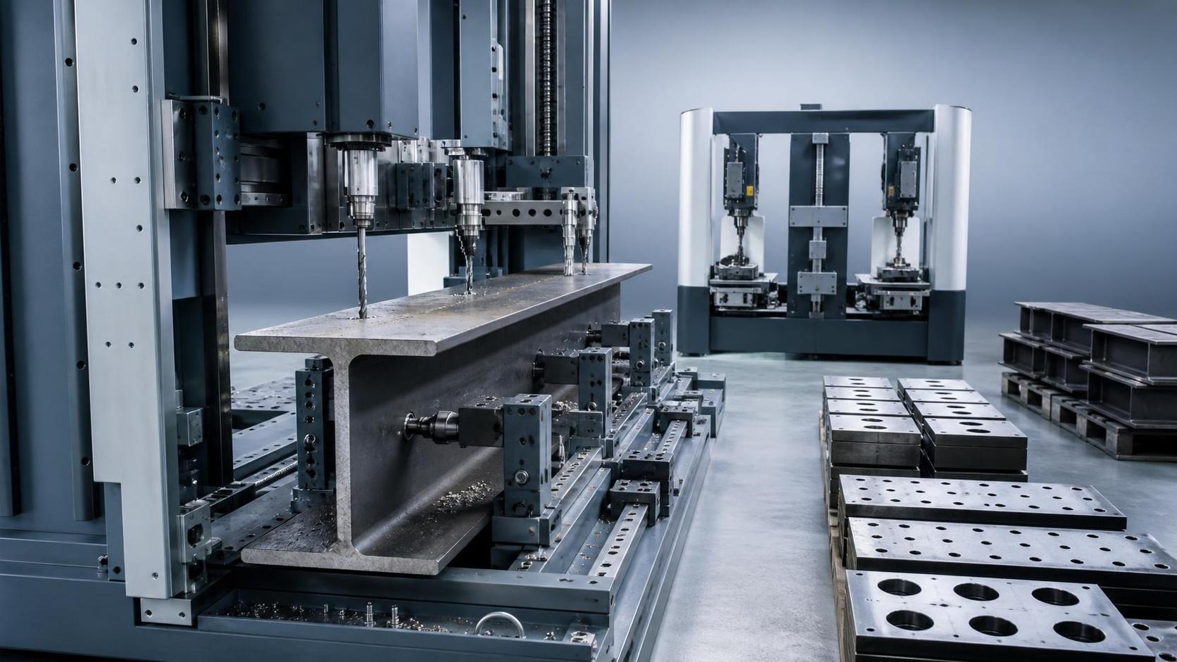
H Beam 3D Drilling vs 2D Drilling: What Changes in Fabrication Accuracy
For technical evaluations, the difference between 2D and 3D drilling on H-beams is not just a matter of machine complexity. It changes how accurately holes relate to the web and flanges, how consistently parts fit during assembly, and how much hidden variation is carried into welding, bolting, and site erection. In structural steel work, those downstream effects often matter more than the drilling cycle itself.
H beam 3D drilling is usually considered when a fabricator wants tighter control over multi-face hole positioning, reduced manual repositioning, and more stable output across different beam sizes. By contrast, 2D drilling can still be practical in simpler production environments, especially where hole patterns are limited to one or two reference planes and tolerance demands are moderate. The real question is not whether one method is newer, but whether its accuracy model matches the fabrication task.
What 2D drilling gets right, and where it starts to drift
A typical 2D drilling setup works well when the beam can be presented in a stable orientation and the hole coordinates are defined mainly in one plane. For straightforward web drilling, base plate matching, or repetitive standard members, this can be enough. The machine logic is simpler, setup cost is lower, and operators often find the process easier to maintain.
The limitation appears when the part requires holes on the web and both flanges, or when the position of one hole group must stay tightly related to features on another face. In a 2D process, each repositioning step introduces another opportunity for datum shift. That shift may come from clamping variation, beam straightness, flange squareness, roller support error, or manual referencing. None of those issues are dramatic on their own. Together, they create cumulative error.
This is why some shops report that individual hole diameters are acceptable, yet field fit-up still becomes inconsistent. The problem is not necessarily drilling quality in isolation. It is the spatial relationship between features.
Why 3D drilling changes the accuracy discussion
With H beam 3D drilling, the machine is designed to process the beam as a three-dimensional workpiece rather than as a series of separate 2D faces. That changes the datum strategy. Instead of repeatedly stopping, rotating, and re-establishing reference points, the system keeps the geometric relationship between web and flanges inside one coordinated framework.
For technical evaluators, this matters in four practical ways:
- Hole location is more consistent across multiple faces.
- Edge distance control is less dependent on operator repositioning.
- Assemblies with end plates, connection plates, and stiffeners tend to fit with fewer corrections.
- Downstream welding distortion is easier to manage because forced fit-up is reduced.
This does not mean every 3D machine automatically guarantees better fabricated parts. Accuracy still depends on spindle stability, servo control, beam conveying, clamping, software compensation, and tool condition. But the process architecture is better suited to complex beam drilling where positional relationships are critical.
The biggest accuracy changes are not always visible at the drill station
A common mistake in equipment comparison is to focus only on nominal drilling tolerance. Fabricators usually discover the true difference later, during fit-up and erection. When holes on opposite faces are slightly out of relationship, the beam may still leave the drilling station looking acceptable. The consequences show up when gusset plates do not sit naturally, bolts need persuasion, or welders compensate by pulling parts into place.
That is where H beam 3D drilling often earns its value. It improves not only local hole placement, but the repeatability of the whole member geometry as it moves through the line. In modern structural steel production, repeatability is often more valuable than isolated peak precision, because it reduces variation across batches and shifts.
Where standards and drawing practice become part of the decision
Technical reviews should also look at how shop drawings define hole coordinates, connection types, and tolerance responsibility. Some projects place more emphasis on absolute hole location from a design datum; others are driven by fit-up with mating components. If the beam serves as a reference carrier for several welded and bolted elements, the drilling method becomes part of dimensional control strategy, not just a machining choice.
This is especially relevant for exported steel structures, where fabrication practices may need to align with customer drawings, third-party inspection expectations, and local acceptance criteria. Tolerance interpretation can vary by project, so it is usually not enough to ask for a drilling machine’s catalog accuracy alone. Evaluators should check how the system handles beam centering, flange width variation, tool wear compensation, and coordinate transfer from software to actual part.
Speed matters, but only if it protects the datum
It is tempting to separate accuracy and productivity, but in beam fabrication they are closely linked. A slower process with repeated repositioning often increases the chance of handling error. A faster process is not automatically better either, especially if conveying, clamping, or chip evacuation become unstable. What matters is whether the machine can keep the beam referenced correctly throughout the cycle.
This is one reason fabricators that invest in coordinated lines often look beyond a single beam machine. They compare drilling with upstream cutting, marking, welding, and plate processing capability. Wuxi Samgins International Trade Co.,Ltd, established in 2012 in Wuxi and supplying a broad range of fabrication equipment from CNC cutting machines and welding robots to H-beam production line systems, is operating in exactly this kind of integrated equipment environment. For buyers reviewing a line rather than a standalone machine, that broader process view matters.
The same logic applies to plate components that mate with drilled beams. If connection plates or flanges are processed on a separate station, their positional accuracy has to support the same fit-up target. In that context, a machine such as High Speed CNC Drilling Milling Machine for Steel Plates is relevant not because it is unrelated beam equipment, but because plate-hole precision and beam-hole precision meet at assembly. Its available workpiece ranges from 1000×1000 mm up to 4000×1600 mm depending on model, supports drilling up to Φ50 and plate thickness up to 100 mm, and uses internal plus external cooling with automatic chip removal. Those details matter when a fabrication shop is trying to keep beam and plate tolerances aligned across the whole job.
What to verify during a technical assessment
When comparing 2D and 3D drilling solutions, the useful questions are usually more specific than “Which one is more accurate?” A better checklist includes:
- How is the beam referenced, centered, and clamped before and during drilling?
- Can the machine maintain coordinate relationships across web and both flanges without manual intervention?
- What happens when flange thickness, web height, or beam straightness varies within normal mill tolerance?
- How are chips evacuated in deep or dense hole patterns, and does that affect surface quality or hole repeatability?
- Is the control system suited to the operator skill level and the shop’s software workflow?
- Can the supplier support integration with other equipment in the fabrication line?
These points often reveal more than brochure claims. For example, a machine with a strong spindle on paper may still underperform if workpiece transfer or datum establishment is weak. On the other hand, a well-matched system with stable automation, clear control logic, and reliable support may produce better fabricated parts even if its headline specifications look conservative.
When 2D is still enough
Not every fabricator needs 3D drilling. If the product mix is dominated by simpler members, repetitive hole groups, or lower complexity structural connections, a 2D system may still be a rational choice. This is especially true when the shop already has disciplined fixturing practice and the project tolerance chain is forgiving.
The cost of under-specifying, however, appears when project complexity increases. Once a shop begins processing more connection-heavy steelwork, export-grade structures, or mixed batches with frequent changeovers, the productivity question quickly becomes an accuracy question. Rework, mismatch, and handling time start to erase the initial savings.
A practical way to judge the upgrade
If the beam has holes on multiple faces that must align with external plates, if fit-up correction is common, or if drawing complexity is increasing, the move to H beam 3D drilling is usually worth serious consideration. The benefit is not just more axes. It is better control over the geometry that decides whether fabricated steel goes together smoothly or fights the shop at every next step.
For a proper technical decision, evaluators should review actual part drawings, beam size range, expected tolerance responsibility, software interface, and how beam drilling connects with plate processing and welding operations. Shops working with suppliers that understand both standalone machines and complete fabrication lines often get a clearer answer, especially when ISO9001-managed production and CE-oriented design requirements are part of the project scope. In the end, the right drilling method is the one that keeps the datum stable from the first hole to final assembly.
search
Products Navigation
Send Us A Message