




H-Beam Welding Robots: Key Parameters for Flange-to-Web Weld Automation
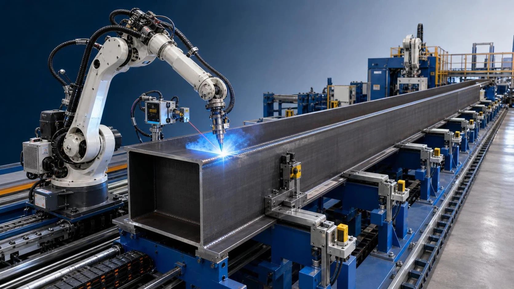
Flange-to-web welding is governed by a chain of geometric, thermal, and motion-control conditions. A welding robot for H beam production must maintain a usable torch angle along long longitudinal fillet welds while the flange and web remain aligned within the allowable fit-up window. Arc travel speed alone cannot establish whether the cell will produce stable welds. Root condition, plate thickness range, joint orientation, wire process, positioner behavior, and the method used to correct real workpiece variation all affect the result.
H-beam lines commonly process components whose nominal dimensions are consistent while actual edge condition and assembly geometry vary from piece to piece. Web centering may shift, flange plates may carry local camber, and gaps can change after tack welding or clamping. The robot, welding power source, gantry, conveyor, and fixture therefore need to be assessed as one process rather than as separate catalog items.
Joint Geometry Sets the Automation Window
The usual flange-to-web connection is a longitudinal fillet weld on both sides of the web. Before selecting a robot system, define the full range of flange width, web height, plate thickness, beam length, and target fillet size. A cell designed around one nominal beam section can become restrictive when the largest web height moves the seam outside the practical wrist envelope or when narrow flanges reduce the clearance available for the torch body and gas nozzle.
Fit-up tolerance should be stated in measurable terms. Relevant conditions include web offset from the flange centerline, root gap between plates, angular deviation, plate edge mismatch, tack-weld height, and allowable beam bow. A rigid programmed path assumes that every assembly presents the seam at the same location. That assumption may be acceptable only when upstream cutting, edge preparation, assembly, and clamping are tightly controlled. Where variation is expected, seam finding before the weld and seam tracking during the weld should be specified as separate functions.
Touch sensing can locate an edge or reference face before arc ignition, but it cannot continuously compensate for movement that develops during welding. Arc-voltage tracking can follow moderate changes in contact-tip-to-work distance after a stable arc is established, subject to the selected welding process and joint configuration. Laser or optical systems may be considered when surface condition, joint access, and expected variation justify them. Their performance depends on clean sensing surfaces and a mounting position protected from spatter and impact.
The fixture has an equal role. Clamps must restrain the web sufficiently to preserve joint geometry without causing excessive local distortion or obstructing the torch. Datum surfaces should match the robot coordinate strategy. If the beam is located from different faces at different stations, coordinate transformations and handoff tolerances need explicit definition. A weld program cannot compensate indefinitely for inconsistent part location.
Welding Process Capacity and Heat Input
The required current range must cover the smallest and largest qualified fillet welds, including start and stop conditions. Gas metal arc welding is common for automated H-beam fillets because it supports continuous wire feeding and long travel paths. The specific transfer mode, wire diameter, shielding gas, polarity, and power-source waveform should be selected through welding procedure development, not from robot payload data.
For thicker material or larger specified fillets, a single pass may be unsuitable or may create an excessive leg profile. Multi-pass deposition raises additional requirements: accurate pass placement, interpass temperature control where required, accessible cleaning between passes, and consistent bead sequencing on both sides of the web. The robot controller should coordinate weld schedules with positioner movement, sensing actions, and any external cleaning or inspection station.
Heat input must be considered together with travel speed and joint restraint. Increasing wire feed to reduce cycle time can increase deposited metal and alter penetration, reinforcement, spatter generation, and distortion. Conversely, a low-current procedure may reduce deposition rate but can become sensitive to mill scale, poor grounding, or variable root opening. Qualification of the intended procedure should represent actual plate grades, thicknesses, joint preparation, and welding positions expected in production.
Arc start and termination require attention on long beams. Poorly controlled starts may leave cold-lap conditions; abrupt stops can form craters or local underfill. Run-on and run-off tabs, programmed lead-in and lead-out motions, crater-fill parameters, and the permitted weld termination location should be coordinated with fabrication requirements. If tabs are used, their removal method must avoid damaging the finished flange or web.
Robot Reach, Payload, and Torch Access
Nominal maximum reach is only a preliminary screening value. The useful working envelope is reduced by torch length, cable dress, collision clearance, manipulator joint limits, and the need to hold a stable work angle. For horizontal fillet welds, the torch normally needs a defined travel angle and work angle; near the ends of a beam, the robot may need to reorient rapidly without allowing the wrist, nozzle, or torch neck to contact clamps and end stops.
A six-axis arm can offer valuable orientation freedom around brackets, diaphragms, stiffeners, and irregular end details. On straightforward long-beam production, however, the longitudinal travel axis or moving carriage frequently determines effective coverage. The arm must be assessed at each critical station: seam start, center section, beam end, and every region where a fixture or support blocks a direct approach.
Payload calculation should include the complete process mass: welding torch, wire feeder when arm-mounted, collision sensor, cable package, anti-spatter accessories, and any tool-changing interface. The quoted payload alone does not indicate whether a robot can maintain dynamic performance at an extended reach. Cable routing also needs practical examination. A cable bundle that twists near an axis limit or rubs against beam edges can create unplanned stops and inconsistent torch orientation.
As an example of the parameters to compare, the Multipurpose Handing Robot BR10iB-15 has a six-axis structure, a 10 kg payload, 1584 mm maximum reach, and stated repeatability of ±0.08 mm. Those values may suit process tooling within a compact welding, handling, or cutting cell, but suitability for a flange-to-web weld still depends on the actual torch package, rail arrangement, beam envelope, and interference study. Ground, side, and hoisted mounting options change access paths as well as foundation and maintenance requirements.
Position Accuracy Versus Weld Path Accuracy
Robot repeatability and absolute position accuracy describe different characteristics. Repeatability indicates how closely the robot returns to a programmed location under stated conditions. Absolute accuracy concerns the difference between commanded and actual positions in the cell coordinate system. For H-beam welding, repeatability may support consistent motion on well-located assemblies, while absolute path performance, calibration quality, fixture stability, and seam sensing determine whether the torch reaches the real joint.
Calibration should cover the robot base frame, tool center point, external axis relationship, workpiece coordinate system, and any sensing device. A small error in tool center point definition changes both nozzle stand-off and torch angle. This becomes more noticeable at the far end of the reach envelope. After torch-neck replacement, collision recovery, rail service, or relocation of a fixture, the applicable calibration records should be reviewed before production resumes.
External axes require synchronized interpolation with the robot. A beam carried through a fixed welding station, a robot travelling on a rail, and a beam rotated on a positioner each produce different control risks. Motion blending at a seam start may be useful for smooth travel, yet it must not begin welding before position and process conditions are stable. Encoder feedback, mechanical backlash, rail straightness, and acceleration limits influence the resulting bead, especially when welding begins close to a direction change.
Seam Tracking Must Match the Real Variation
Tracking capability is sometimes specified broadly even though its useful range is limited. The expected lateral and vertical seam deviation, the response speed required, the type of joint, and the surface state should be defined before selecting a sensor. Heavy mill scale, primer, moisture, oil, and slag from tack welds can affect sensing reliability and welding stability at the same time.
- Pre-weld search is appropriate where each beam is held securely and the seam remains stable after the reference points are found.
- Through-arc correction can address moderate path variation during welding when the electrical signal remains sufficiently stable and the welding procedure supports reliable interpretation.
- Vision-based sensing may support more variable assemblies, but its field of view, cleaning method, protective window, and response to changing surface reflectivity need validation on representative material.
Tracking should not be used to mask defects created upstream. A web that is grossly displaced, an intermittent root gap, or a tack weld standing in the intended torch path can exceed the correction range or produce a weld that appears continuous while failing dimensional or fusion requirements. Establishing reject conditions before automated welding prevents the robot from processing assemblies that require rework first.
Production-Line Interfaces and Material Flow
An H-beam welding cell is constrained by material flow as much as by arc-on time. Infeed conveyors must support the beam without inducing a change in joint gap. Roller spacing, support height, transfer alignment, and stop position should be suitable for the longest and heaviest assemblies in the intended range. A long, flexible beam may sag differently between supports, changing torch stand-off along its length.
Handshake signals between the assembly station, robot controller, welding source, conveyor, safety system, and outfeed equipment should define the sequence clearly. Essential states usually include part present, part clamped, correct program selected, external axis ready, welding source ready, fault active, weld complete, and release permitted. Program selection should be tied to identifiable workpiece data or a controlled manual confirmation method. Allowing an incorrect beam recipe to run can produce a geometrically plausible but nonconforming weld.
Where two longitudinal seams are welded in sequence, heat balance and release timing matter. Welding one side fully before the other can pull the web or flange depending on section geometry and restraint. Alternating sides, using balanced passes, or managing the sequence through multiple stations may be appropriate, but the final approach should follow the qualified procedure and observed distortion behavior. The beam must remain restrained until the sequence permits release.
Quality Control at the Cell Boundary
Automation does not remove the need to define acceptance criteria. Dimensional checks before welding should address section assembly, squareness, web centering, and tack condition. During the weld, process monitoring can record current, voltage, wire-feed condition, travel speed, gas flow status, arc time, and fault events. Such records are useful only when associated with a part identifier and retained in a form that supports traceability where it is required.
Visual examination after welding should consider leg size, throat-related requirements where applicable, bead continuity, undercut, overlap, porosity indications, spatter condition, start and stop quality, and distortion. The inspection method, sampling basis, and any required non-destructive examination should be established by the governing fabrication specification and welding procedure. A robot system should allow safe access for gauges and inspection equipment without forcing measurements over hot material or inside guarded motion zones.
Rework routing deserves a defined physical path. Removing a beam from the normal flow, identifying the affected seam location, performing repair under an approved procedure, and returning the beam without losing its production record are practical issues. Treating rework as an exception outside the cell design often leads to blocked conveyors and ambiguous traceability.
Installation Conditions and Service Access
Foundation stiffness, rail alignment, cable containment, welding return-current routing, ventilation, and guarding influence long-term repeatability. The welding return path should be arranged to avoid unintended current paths through bearings, linear guides, sensors, or controller grounding circuits. Welding cables need protected routing with adequate bend radius and a route that permits axis motion across the full programmed envelope.
Ambient conditions also affect equipment selection. A robot specified for a given temperature and humidity range still requires protection from condensation, conductive dust, abrasive grinding particles, and direct weld spatter. An enclosure can reduce contamination, but it must not obstruct cooling or make routine service impractical. Space is needed to replace contact tips, liners, wire spools, torch necks, sensor covers, and drive components without dismantling fixtures.
Preventive maintenance should focus on conditions that change the weld path: torch consumable wear, nozzle buildup, liner drag, wire-feed roller condition, cable damage, TCP drift, fixture wear, loose clamps, and rail contamination. Monitoring these items against actual production hours and fault history is generally more useful than relying only on a calendar interval. The final selection should document the permitted beam range, qualified process envelope, sensor limits, external-axis accuracy, and recovery method after a collision or interrupted weld. Those boundaries determine whether a welding robot for H beam fabrication remains stable when production conditions depart from the ideal part.
search
Products Navigation
Send Us A Message