




How Welding Robots Improve Circumferential Seam Quality in Pressure Vessels
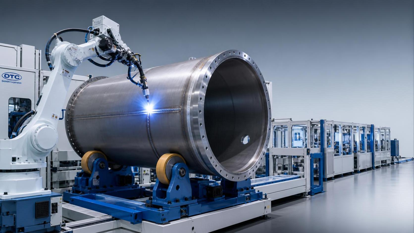
Why Circumferential Seams Deserve Separate Control
For quality-control and safety teams, circumferential seams are not simply another weld category on a fabrication drawing. They are often the joints that define the pressure boundary of a shell course, head-to-shell connection, nozzle neck, or cylindrical component. A defect that might be tolerable in a non-pressure structural weld can have very different consequences when it sits in a vessel expected to withstand repeated pressure cycles, elevated temperature, corrosive media, or demanding inspection requirements.
That is why the question is rarely whether a welding robot can produce an acceptable bead under ideal conditions. The real question is whether a welding robot for pressure vessels can make the complete welding process more repeatable, more observable, and easier to control than a manually dependent process.
In practical vessel production, circumferential seam quality is affected by more than the welding arc. Fit-up variation, ovality of the shell, tack-weld condition, joint cleanliness, consumable control, rotation stability, gas coverage, and the chosen welding procedure all influence the final result. Robotic welding can reduce variation in several of these areas, but it cannot compensate indefinitely for poor upstream preparation or an unstable production process.
What Robotic Welding Changes in the Weld Cycle
A conventional manual circumferential weld may depend heavily on an operator maintaining torch angle, travel speed, arc length, weave pattern, and attention over a long welding cycle. Skilled welders can produce excellent results, but consistency can vary between shifts, operators, vessel sizes, joint positions, and fatigue conditions. The difficulty increases when production involves repeated shells or when seams are long enough that small changes in technique accumulate into measurable variation.
A robot does not remove welding metallurgy from the process. It does, however, provide a more controlled way to execute the approved procedure. Once the welding parameters and motion path have been qualified for a defined joint configuration, the system can repeatedly control:
- torch travel speed around the circumference;
- torch-to-work distance and programmed torch orientation;
- arc start, stop, crater-fill, and overlap behavior;
- wire-feed settings, voltage, current, and pulse parameters where applicable;
- weave width, dwell time, and layer sequence for multi-pass joints;
- coordinated movement between the robot and vessel turning rolls or positioner.
For a quality team, this changes the nature of process risk. The operation is no longer dependent primarily on individual hand movement. Instead, the focus shifts toward programmed parameters, mechanical setup, sensor reliability, joint presentation, and the discipline used to manage welding procedure changes. This is generally a more auditable environment, provided that the manufacturer treats robot programs as controlled production documents rather than informal shop-floor settings.
Consistency Is Valuable, but Only Within a Stable Window
The most visible benefit of robotic welding is usually bead consistency. Stable travel speed and torch position can help maintain a more uniform weld profile, especially on repetitive circumferential joints with similar diameter, thickness, groove preparation, and welding position. Consistent heat input can also support more predictable penetration and reduce the tendency for local undercut, irregular reinforcement, excessive spatter, or uneven bead width.
However, “consistent” does not automatically mean “compliant.” A robot can consistently make the same unacceptable weld if the programmed procedure, joint geometry, or setup condition is wrong. This is an important distinction for safety managers reviewing automation proposals. The value of the system comes from repeatability combined with validation, monitoring, and response rules when the actual process departs from the qualified range.
For example, a robotic cell may be programmed for a nominal root gap and bevel angle. If fabricated shells arrive with inconsistent gap, mismatched edges, or variable root-face dimensions, the robot may encounter lack of fusion, burn-through, incomplete penetration, or poor root contour. Seam tracking and adaptive controls can extend the process window, but they should not become an excuse to relax fit-up inspection.
Before approving automation, production and quality teams should establish which variables are controlled before welding and which are expected to be corrected during welding. In pressure-vessel work, the first group should remain substantial: material identification, edge preparation, dimensional alignment, tack quality, cleanliness, and joint accessibility should be confirmed before the automated cycle starts.
Common Circumferential Defects and Where Automation Helps
Robotic welding is especially useful where recurring process variation is the primary cause of defects. The table below separates areas where automation can materially improve control from areas that still need direct fabrication discipline.
The strongest applications are usually repetitive production families: similar shell diameters, recurring wall-thickness ranges, standardized joint designs, and predictable welding access. A fabrication shop producing one-off vessels with large variations in diameter, material grade, nozzle arrangement, or internal obstruction may still benefit from a robot, but the programming and handling burden becomes more significant. In that environment, a flexible cell with quick tooling change, seam finding, and robust process engineering is more important than headline robot speed.
The Positioner Is Part of the Quality System
When discussing robotic circumferential welding, attention often goes to the robot arm, power source, and welding package. For vessel seams, the workpiece handling system is equally important. Turning rolls, rotators, headstocks, tailstocks, and positioners determine whether the joint is presented to the torch at a stable, repeatable orientation.
Variation in vessel rotation can lead directly to variation in effective travel speed. Runout, slippage, eccentric loading, and inconsistent rotation acceleration are not merely mechanical inconveniences; they can affect weld appearance and heat distribution. A cell should therefore be assessed as an integrated system. The robot, welding power source, wire feeder, workpiece rotator, safety interlocks, and process controls must be coordinated and validated together.
For long cylindrical shells, shop teams should check whether rotation is synchronized with robot motion or whether the robot remains substantially fixed while the vessel rotates. Both concepts can work, but the control strategy must match the seam type and tolerance requirements. The important point is to avoid a situation in which robot motion is stable but the workpiece movement is not.
Shell ovality also deserves early attention. A circular path generated from nominal CAD dimensions may not follow the actual joint accurately when the vessel is out of round or when fit-up differs from the assumed geometry. Touch sensing, laser seam tracking, through-arc sensing, or other adaptive methods may be appropriate, depending on the welding process and joint configuration. Their performance should be demonstrated on representative parts, including realistic fabrication variation, rather than only on a perfectly prepared test coupon.
Traceability Becomes More Useful When It Is Designed In
Pressure-vessel quality assurance normally requires more than a visually acceptable weld. The organization may need to demonstrate that the correct approved procedure was used, relevant personnel were qualified, materials and consumables were controlled, inspections were completed, and nonconformities were managed. Exact documentation requirements depend on the applicable code, customer specification, jurisdiction, and certification route, so the governing requirements should be confirmed for each project.
Robotic systems can strengthen this framework because they can capture process information automatically. Depending on the equipment and integration level, available records may include program identification, weld date and time, operator login, current and voltage trends, wire-feed speed, travel speed, alarm history, cycle interruption, and selected parameter changes. Not every stored data point is equally meaningful, and not every system provides evidence adequate for code compliance on its own. Still, these records can make investigation faster when an inspection result is questioned later.
Quality managers should avoid collecting data simply because the controller makes it available. A useful traceability plan defines which records are tied to the weld number, who can change the program, when a change requires requalification or engineering review, and what happens when monitored values exceed established limits. Without those rules, a production cell can generate large volumes of information without improving control.
A practical minimum is to link each production seam to the applicable welding procedure, robot program revision, material heat or batch records where required, filler-metal batch, weld operator or cell operator, inspection status, and repair history. Where the process is automated, the approved robot program should be subject to controlled access and revision management. A small unrecorded adjustment to speed, voltage, weave, or start-stop sequence can matter more than its size suggests.
Upstream Edge Preparation Still Determines the Starting Point
Automation is often introduced at the welding station while upstream preparation remains variable. This is a common source of disappointing results. If cut plates, shell segments, reinforcement pads, support brackets, or auxiliary fabricated components arrive with burrs, slag, scale, sharp edges, or inconsistent finishing, handling and fit-up quality may suffer before welding begins.
For sheet-based supporting parts produced by laser, plasma, flame cutting, shearing, or stamping, a controlled deburring stage can reduce handling hazards and improve consistency before assembly. Equipment such as the RNS1000 Sheet metal deburring machine is relevant in this upstream context because it is designed for all-direction edge and hole deburring, surface finishing, descaling, and slag removal on metal sheets. It should not be confused with a solution for preparing the pressure-retaining circumferential groove itself; groove geometry and root-face preparation for vessel welding need their own qualified machining, forming, cutting, or edge-preparation controls.
This distinction matters. A shop may gain safety and handling benefits by removing burrs from fabricated components, while the vessel seam itself still requires dedicated checks for bevel angle, land, root opening, alignment, and contamination. Treating all “edge preparation” as the same process can create gaps in the inspection plan.
Safety Benefits Depend on Cell Design, Not Just Automation
Robotic welding can remove personnel from prolonged exposure to arc radiation, heat, fumes, awkward posture, and repetitive torch handling. For circumferential welding on larger vessels, it may also reduce the need for personnel to work in difficult positions around rotating workpieces. These are meaningful safety advantages, particularly where production volume is high or the geometry encourages uncomfortable manual welding posture.
But the safety profile changes rather than disappears. Automated cells introduce hazards associated with robot motion, rotating vessels, pinch points, wire-feed equipment, hot surfaces, electrical power, and unexpected restart. The safety review should cover normal production, loading and unloading, program proving, torch cleaning, wire replacement, fault recovery, maintenance, and manual jog operations.
Key measures typically include physical guarding, interlocked access points, appropriately designed emergency stops, controlled restart logic, lockout/tagout procedures, safe loading methods, and clear responsibility for cell recovery after a fault. The integrity of safety circuits and interlocks should be periodically tested, not assumed. A safety manager should also verify that production pressure does not lead operators to bypass safeguards during fit-up correction or minor troubleshooting.
How to Evaluate a Welding Robot Proposal
A sound procurement decision should begin with the vessel family, not the robot brand. Quality and safety teams should ask for a demonstration using representative material thickness, joint type, diameter range, tack condition, and expected fit-up tolerance. A demonstration on a simple sample ring may show that the arc works; it does not prove that the proposed system can handle the factory’s actual variability.
- What seam types, diameters, wall thicknesses, and material grades are within the validated operating range?
- How is shell ovality or joint offset detected and managed?
- What are the accepted limits for root gap, mismatch, tack configuration, and joint cleanliness?
- Which process parameters are locked, monitored, and recorded?
- How are robot programs named, approved, backed up, and revision-controlled?
- Can the cell support the applicable welding procedure qualification and inspection plan?
- What happens after an arc interruption, wire-feed fault, seam-tracking loss, or rotator fault?
- How will non-destructive examination findings be fed back into program and fit-up improvement?
- What maintenance, calibration, spare parts, and technical support are available during production?
The last point is often underestimated. A robotic cell that produces excellent qualification welds but experiences frequent downtime, uncertain spare-part supply, or poorly supported software changes can create production risk. For international equipment procurement, buyers should clarify documentation language, electrical and safety conformity requirements, local service capability, operator training, and the scope of factory acceptance testing before shipment.
Use Inspection Results to Improve the Process, Not Only Release the Vessel
The best implementation model connects robotic welding data with inspection feedback. Visual examination, dimensional checks, radiographic testing, ultrasonic testing, penetrant testing, magnetic-particle testing, and pressure testing may each reveal different aspects of weld performance, depending on the vessel design and governing requirements. The goal is not to replace examination with automation. It is to use a more stable welding process so inspection findings become more meaningful and corrective action becomes more targeted.
If recurring indications appear at the same clock position, start-stop point, layer transition, or diameter range, the production team should investigate the full system: positioner behavior, seam-tracking response, joint fit-up, program logic, consumables, shielding gas, and operator intervention records. Repeated repairs should never be treated solely as a welder-performance issue when the cycle is automated. They are process signals.
For pressure-vessel manufacturers, robotic circumferential welding is most effective when it is treated as a controlled manufacturing system rather than a labor-saving machine. The investment is justified where repeatability, traceability, reduced exposure, and stable production quality can be demonstrated on real vessel configurations. The quality decision is therefore not “manual or robot.” It is whether the factory can control the entire chain well enough for automation to make the pressure boundary more predictable.
search
Products Navigation
Send Us A Message