




Selecting a Welding Robot for Tank Fabrication: Capacity, Reach, and Fit-Up
Selecting a Welding Robot for Tank Fabrication: Capacity, Reach, and Fit-Up
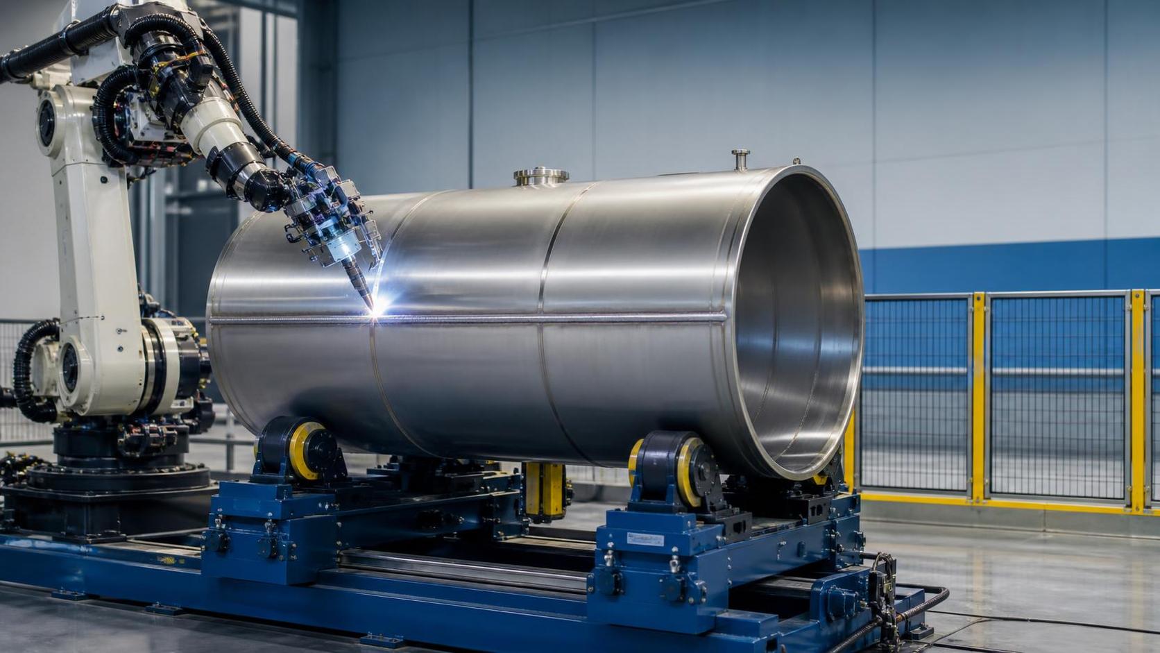
Selecting a welding robot for tank fabrication requires more than comparing robot brands, arc packages, or advertised cycle times. Tank work combines long circumferential seams, changing diameters, shell-to-head joints, nozzles, supports, and variable plate conditions. A robot that performs well on a fixed, clean coupon may still struggle when a shell is slightly out of round, tack welds vary, or the fixture presents the joint at an awkward angle.
For a technical evaluator, the real question is not simply whether a welding robot for tank fabrication can make an acceptable weld. It is whether the complete cell can maintain weld access, process stability, and repeatable part handling across the range of vessels the workshop actually produces. Capacity, reach, fit-up tolerance, positioner behavior, and programming strategy must be considered as one system.
Begin with the Tank Family, Not the Robot Catalogue
The most useful starting point is a practical part-family review. Record the minimum and maximum shell diameter, vessel length, wall thickness, material grades, seam types, and annual or weekly production mix. Include the largest eccentric load, such as a shell with fittings already attached, rather than using the nominal shell weight alone. A system sized only for the average tank may become a bottleneck whenever a heavier or less balanced assembly enters production.
It is also important to separate welds that are genuinely suitable for robotic repetition from welds that remain highly variable. Longitudinal seams and girth seams on repeated shell dimensions are often strong automation candidates. Complex reinforcement pads, densely clustered nozzles, repair work, and one-off components may require a more flexible strategy, additional sensing, or a manual station beside the robotic cell. Trying to automate every weld can make the cell unnecessarily complicated and difficult to recover after normal production variation.
A tank fabricator should map the full route: plate preparation, rolling, tack-up, alignment, welding, inspection, handling, and downstream finishing. If shell roundness and edge preparation are inconsistent before welding, even a capable robotic system will spend time compensating for defects created upstream. The robot should not be used as a substitute for disciplined fit-up.
Payload Capacity Includes More Than the Welding Torch
Robot payload is often misunderstood. The required capacity includes the torch, wire feeder or torch-mounted components, cable dress package, anti-collision device, seam-tracking sensor if used, and any special tooling. More importantly, capacity must be checked at the required wrist orientation and reach. A robot may have sufficient rated payload on paper but face reduced practical performance when the arm is extended around a large vessel or when cable forces affect wrist movement.
For tank fabrication, the larger mass concern is usually not the robot arm but the workpiece manipulator. Turning rolls, headstock-tailstock positioners, or custom fixtures carry the shell and must handle the maximum calculated load, centre-of-gravity offset, and inertia during starts and stops. A heavy vessel that rotates smoothly at constant speed can still impose substantial demands during acceleration, deceleration, or emergency stopping.
The load calculation should include fixtures, temporary strongbacks, and mounted accessories. It should also distinguish between a balanced cylindrical shell and a partially assembled vessel with nozzles or support legs. Where the assembly is off-centre, the integrator should assess rotation stability rather than assuming that a nominal tonnage rating tells the whole story.
Reach Must Be Verified in the Real Welding Envelope
A long robot reach is useful, but maximum reach is not the same as useful welding reach. Near the outer boundary of its envelope, a robot can encounter unfavourable wrist angles, lower path quality, difficult cable routing, or collision risk with the shell, rolls, clamps, and safety guarding. The critical assessment is whether the torch can maintain the required work angle, travel angle, and stick-out through the entire seam.
For external girth welding, rotation of the tank often allows the robot to work within a comfortable zone while the joint moves beneath the torch. This can be more reliable than asking the robot to travel a large circular path around a stationary shell. Internal seams change the equation: access diameter, manway size, ventilation arrangements, torch body dimensions, and collision clearance can all limit feasibility. A robot that easily reaches the exterior may not be a practical solution for interior welding.
Offline simulation is valuable when the vessel range is broad, but it should be based on realistic models. Include tack welds, clamps, nozzle protrusions, rotating equipment, torch-cleaning stations, and the actual base or rail arrangement. Simulation can identify a problematic approach angle before equipment is ordered, although a physical run-off on representative parts remains important for confirming arc behavior and fit-up response.
Positioning Often Decides Weld Quality
The most productive robotic welding cells do not ask the robot to solve every geometric problem. They place the weld in a favourable position and allow controlled workpiece rotation to create a stable welding condition. This matters particularly for circumferential seams, where consistent rotation supports a uniform travel speed and reduces the need for repeated changes in robot posture.
A rotator should therefore be evaluated as part of the welding system, not as a separate handling purchase. Its speed range, speed stability, wheel material, adjustable roller spacing, load distribution, and interface with the robot controller all affect the seam. For cylindrical assemblies and pressure-vessel work, a Lead screw welding rotator can provide controlled positioning where the roller-centre distance needs to suit different diameters. The CHGK series is offered from CHGK-2 through CHGK-60, with stated centre-distance ranges varying by model from 280–950 mm to 900–2100 mm.
The supplied rotator information indicates stepless frequency-conversion speed regulation and a remote hand control box with forward, reverse, and speed-setting functions. Its stated rotation range is 100–1000 mm/min in the functional description. Because equipment documentation may express linear roller speed and rotational conditions differently, the required speed range and synchronization method should be confirmed against the actual tank diameter and welding procedure before final selection. For robotic circumferential welding, the key issue is stable, repeatable surface travel at the programmed weld speed.
Fit-Up Tolerance Is the Real Test of Automation
A robot follows a programmed path very well; it does not automatically know where a drifting joint has moved. In tank fabrication, joint location can change because of plate rolling variation, shell ovality, mismatch at the seam, thermal distortion, inconsistent tack-up, or variation in root opening. These conditions determine whether a basic teach-and-repeat cell is adequate or whether seam finding and adaptive tracking are justified.
Through-arc seam tracking can be useful during welding when the process and joint geometry support reliable electrical feedback. Laser vision or tactile searching may be appropriate where the start point or joint position varies before welding. Neither option is a cure for excessive gaps, contaminated edges, poor tack placement, or fundamentally inconsistent preparation. Sensors add capability, but they also introduce calibration, maintenance, and programming requirements.
The better decision is to define acceptable incoming variation before specifying sensors. Ask production and quality teams to document expected mismatch, root-gap range, seam wander, and out-of-round condition for each tank family. Compare these conditions with the qualified welding procedure and the robot supplier’s demonstrated tracking limits. If variation exceeds what the weld procedure can tolerate, the first investment may need to be better edge milling, rolling control, fit-up tooling, or tack welding discipline.
Questions worth asking during a technical review
- Can the robot maintain the required torch angles at every point on the largest and smallest tank?
- What is the maximum combined weight of the vessel, fixture, attachments, and temporary supports?
- How will robot motion and tank rotation be synchronized during a girth seam?
- What fit-up variation is normal on the shop floor, rather than ideal in a drawing?
- Which seam-tracking method is being proposed, and under what joint and process conditions has it been validated?
- How are welding fumes, spatter, torch cleaning, wire changes, and access for maintenance handled in the layout?
Match the Arc Process to Material and Joint Requirements
Robot choice cannot be separated from welding process selection. Carbon-steel storage tanks, stainless process vessels, and thicker pressure-retaining shells can demand different deposition rates, heat-input control, shielding arrangements, and finishing expectations. GMAW is common where deposition rate and automation compatibility are priorities, while other processes may be selected for specific material, thickness, or quality requirements. The correct approach depends on the approved welding procedure, applicable code requirements, and customer specifications.
A proposed cell should demonstrate the intended process on representative material, joint preparation, and welding position. Evaluators should look beyond bead appearance. Review starts and stops, crater treatment, tie-ins, distortion, access for inspection, and whether the weld remains repeatable after normal production interruptions. If the tank requires post-weld cleaning or dressing, that operation should be included in cycle-time and handling planning instead of being treated as an afterthought.
Integration, Safety, and Recovery Matter as Much as Programming
A welding robot cell must communicate clearly with rotators, positioners, safety equipment, and any upstream or downstream handling system. Define who controls cycle start, rotation enable, fault acknowledgement, emergency stop behavior, and safe speed. A well-designed sequence prevents the torch from entering the weld zone before the vessel is clamped and prevents rotation from starting while an operator has access to the hazardous area.
Recovery after a fault deserves early attention. A production team needs an understandable method for resuming after wire burn-back, a gas interruption, a collision trip, or a planned operator intervention. If recovery requires a specialist programmer every time, the practical availability of the cell will suffer. Training should cover not only normal operation but also teaching touch-ups, consumable replacement, calibration checks, and safe restart procedures.
For projects serving different export markets, documentation, electrical configuration, guarding, and conformity expectations should be reviewed during engineering rather than immediately before shipment. Wuxi Samgins International Trade Co.,Ltd, established in 2012 in Wuxi, Jiangsu Province, supplies automatic welding equipment, welding robots, cutting systems, machine tools, plate-processing equipment, and H-beam production machinery. Its equipment is organized around ISO9001 quality-system practices, and CE-supported products are available for applications requiring European-market consideration. The final compliance assessment still needs to match the specific machine configuration and destination requirements.
A Sound Selection Is a Balanced Cell
The right welding robot for tank fabrication is rarely identified by one headline specification. It is a balanced cell in which robot reach, torch access, tank rotation, fixture accuracy, weld procedure, and operator recovery procedures support one another. Oversizing the robot while under-specifying the rotator, or adding advanced sensing while accepting poor shell fit-up, merely moves the limitation elsewhere.
Before releasing a purchase decision, ask for a layout based on the largest and smallest vessels, a load and inertia review for the handling equipment, a description of the proposed tracking method, and a demonstration plan using representative joints. Confirm the interface responsibilities between robot, welding power source, rotator, safety system, and installation team. Those checks turn an attractive automation concept into a tank welding cell that can be operated consistently on the workshop floor.
search
Products Navigation
Send Us A Message