




How blade clearance affects cut quality on a shearing machine
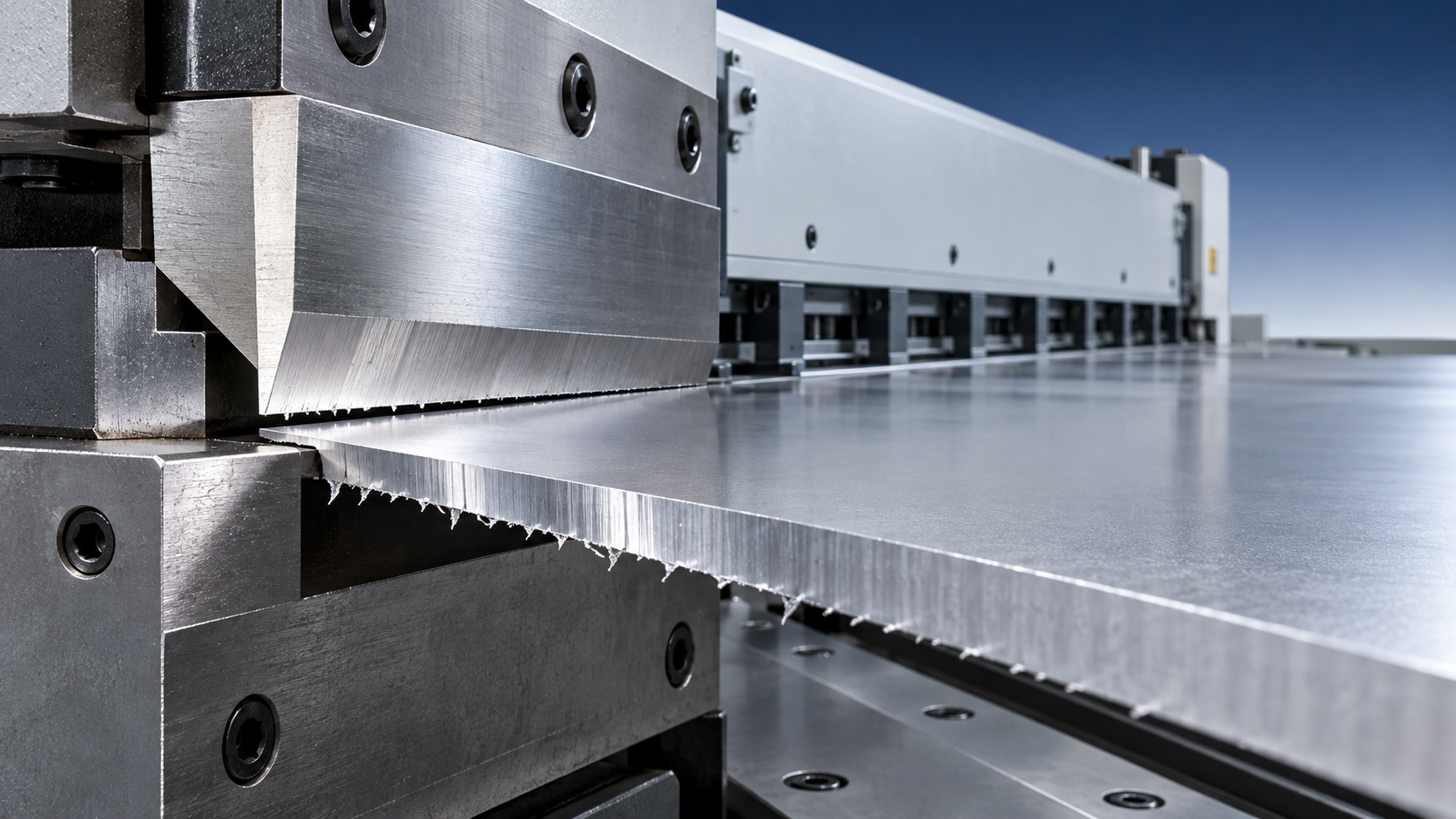
A shearing machine can have sharp blades, a sound hydraulic system, and a correctly positioned backgauge, yet still produce unacceptable parts when blade clearance is wrong. The first signs are usually visible at the edge: a wide burr on the underside, a heavily rolled top edge, a rough fracture zone, or a cut line that seems to wander. In a production area, those defects do more than affect appearance. They can interfere with fit-up, create handling hazards, damage downstream tooling, and force operators to spend extra time deburring.
The basic rule is straightforward: blade clearance must match the sheet thickness, material strength, and actual condition of the blades. Too little clearance compresses and tears the sheet instead of allowing a controlled shear. Too much clearance increases bending and fracture separation, leaving a larger burr and a rougher edge. The correct setting produces a clean burnished zone, a controlled fracture line, limited distortion, and a burr that is small enough for the part’s intended use.
What blade clearance actually controls
Blade clearance is the gap between the upper moving blade and lower fixed blade during the cutting stroke. It is not simply an empty space. It determines how the material is stressed before it separates.
During a normal shear, the upper blade first presses into the sheet. The material plastically deforms near the cutting line, then begins to crack from the upper and lower edges. When clearance is appropriate, those fracture paths meet in a controlled way. The result is a cut edge with two recognizable areas: a relatively smooth, shiny burnished section created by blade penetration, followed by a rougher fracture section where the material separates.
When the setting moves outside the suitable range, the two fracture paths no longer meet correctly. The sheet may be squeezed, bent, stretched, or torn apart. The visible edge condition becomes a useful diagnostic tool because it records what happened during the cut.
How too little clearance affects the cut
A very tight gap can seem like a safe choice because it appears likely to create a finer cut. In practice, insufficient clearance often overloads the cutting zone. The blades press the sheet aggressively before fracture develops, increasing cutting force and placing extra stress on the machine frame, hold-down system, blade mounts, and drive components.
The edge may show a large polished or burnished area with a secondary tearing line. Rather than separating cleanly, the material can be pulled and dragged between the blades. Thin sheet may curl or become locally distorted near the cut. Coated material can show cracking or flaking around the edge because the coating is strained beyond its ability to follow the substrate.
From a safety perspective, a tight clearance deserves attention for several reasons:
- Higher cutting force can accelerate blade wear and increase the risk of mechanical overload.
- Material may stick, drag, or move unpredictably after the stroke, particularly when narrow strips are cut.
- Damaged or rolled edges can remain sharp even when the burr appears small.
- Operators may be tempted to reach into the cutting area to remove trapped offcuts, which should never be treated as a normal operating step.
A tight setting is especially problematic when a machine is adjusted for thin, mild steel and then used for a thicker or stronger sheet without resetting the gap. Stainless steel, high-strength steel, and some aluminium grades can respond very differently from mild steel of the same thickness.
What happens when the gap is too wide
Excessive clearance gives the sheet more room to bend before it fractures. The upper blade pushes material downward, while the lower blade provides insufficient opposing support. The result is often a pronounced burr on the lower edge, a wider rough fracture zone, and more distortion at the cut line.
Quality inspectors often notice the problem first during assembly. A sheared blank may appear dimensionally correct on a flat table, but its edge can prevent close contact in a welded seam, create inconsistent gaps in a formed component, or interfere with a mating surface. Burrs also create a direct cut hazard during manual handling. Gloves reduce exposure but do not eliminate the need to control the source of the burr.
Wide clearance can also create poor strip behavior. Narrow offcuts may twist, drop unevenly, or spring away from the cutting line. This can affect the safety of material collection and increase the chance of scratches on finished surfaces. On long cuts, poor clearance may make edge quality appear worse toward one side of the sheet, although uneven blade gap, blade wear, or machine alignment may also be involved.
Reading the edge before changing the setting
Changing the clearance without examining the cut edge can hide the real cause. A burr does not automatically prove that the gap is too large, and a shiny edge does not automatically prove that the gap is too small. Blade condition, blade rake angle, sheet flatness, hold-down pressure, material grade, and machine alignment all affect the result.
A practical inspection starts with several cuts from the same material batch. Check both ends and the middle of a long cut, then compare the upper and lower edge condition. Look for the following patterns:
Inspecting only one short sample can be misleading. A nicked section of blade may create one localized defect, while a general clearance error tends to remain visible over much of the cutting length. Where the machine has a manually adjusted gap, each adjustment point should be checked rather than assuming both sides move equally.
Use material properties, not thickness alone
Many machine manuals provide a starting clearance as a percentage of sheet thickness. That approach is useful, but it is only a starting point. The same nominal thickness can require different treatment depending on tensile strength, hardness, ductility, surface condition, and coating.
Softer, more ductile materials may tolerate a different gap from harder or higher-strength materials. A setting that gives acceptable results on low-carbon steel may create excessive burrs on aluminium or heavy edge deformation on stainless steel. Conversely, a harder material can require a different clearance to prevent abnormal blade loading and irregular fracture.
Material thickness must also be verified rather than assumed from a job label. Nominal sheet thickness, actual supplied thickness, protective film, paint, galvanizing, and laminated surfaces can all affect the cutting condition. The film itself is not normally the basis for clearance selection, but it may alter how edge damage is judged. A coated sheet with an acceptable metal fracture may still fail inspection if the coating cracks excessively beside the cut.
Rake angle changes the feel of the cut, but does not replace correct clearance
On many guillotine-style machines, blade rake angle is adjustable. Increasing rake angle reduces the instantaneous cutting force because the blade engages the sheet progressively. This can be useful for thicker plate. However, greater rake can also increase sheet twist, bowing, or distortion, especially on narrow strips. Reducing rake may improve flatness on some materials but increases the force required.
Clearance and rake angle should therefore be considered together, but they solve different problems. Clearance controls the fracture relationship between the blades. Rake angle controls how the blade enters and travels through the material. Adjusting one to compensate for an incorrect setting of the other often creates a new defect elsewhere.
A controlled adjustment process
Before any clearance adjustment, stop the machine according to the site’s lockout and isolation procedure. Do not place hands, gauges, or tools between blades merely because the pedal is released or the control appears inactive. The upper blade must be secured in a safe position, stored energy must be controlled, and only authorized personnel should perform mechanical adjustments.
- Identify the job material. Confirm actual thickness, material type, and whether the sheet has a coating, protective film, or unusual surface condition.
- Check the current blade condition. Look for nicks, rounded edges, chipped sections, loose blade clamping, and debris on blade seats. Clearance adjustment cannot correct a damaged cutting edge.
- Refer to the machine manufacturer’s guidance. Use its recommended setting range as the primary reference for the machine design and intended material capacity.
- Set clearance evenly. On machines with separate left and right adjustments, set both sides carefully. Uneven clearance is a common reason for different edge quality across the sheet width.
- Make controlled test cuts. Use representative scrap from the actual job where possible. Examine the cut edge before releasing production material.
- Record the accepted setting. Note the material, thickness, blade condition, clearance reference, rake angle if relevant, and observed edge quality. This creates a useful baseline when the same job returns.
Do not make large adjustments based on a single defect. If the burr is localized, inspect the blade first. If the problem appears only with one coil or sheet batch, material variation or residual stress may be contributing. Small, documented changes are easier to evaluate and less likely to create avoidable machine loading.
Blade wear can imitate a clearance problem
As blades wear, their cutting edges become rounded. The material is then compressed for longer before fracture begins, which increases force and can produce burrs, rough edges, and distortion even when the indicated clearance is unchanged. Operators sometimes respond by tightening the gap, but that may increase blade contact and accelerate damage.
Blade maintenance should include more than visual inspection. Check whether blades are seated correctly, whether clamping bolts are secure, and whether shim surfaces are clean and undamaged. A blade that has been rotated or replaced may require a full clearance reset. The blade geometry can change after regrinding, so a previous setting should not automatically be reused without a sample cut.
Where permitted by the machine design, reversing or rotating multi-edge blades can extend usable blade life. The process must follow the equipment instructions because incorrect orientation, torque, or seating can create misalignment. A blade change is also an opportunity to inspect hold-down pads, backgauge movement, squaring arms, and offcut handling arrangements.
Quality acceptance should reflect the next operation
Not every part requires the same edge finish. A concealed structural blank may accept a different burr level from a panel that will be handled frequently, precision welded, powder coated, or fitted against a sealing surface. The acceptance standard should be tied to the downstream process rather than judged only by appearance.
For welding preparation, excessive burrs can prevent stable contact between parts and complicate fit-up. Edge contamination and sharp protrusions may also interfere with consistent positioning. In cylindrical fabrication, plate cut quality affects subsequent rolling, seam preparation, and assembly. Once a shell is prepared for welding, equipment such as a Bolt adjusting welding rotator may support controlled rotation of cylindrical workpieces, but it cannot correct inaccurate blank dimensions, twisted edges, or burrs introduced at the shearing stage.
For parts that will be bent, a poor sheared edge can become more visible after forming. Cracks may initiate at a damaged edge, especially where material is already under strain. For painted or coated components, inspect whether the cut produces coating separation that would require edge treatment before the next process.
When the issue is not solved by clearance adjustment
Persistent poor cut quality after a correct, even clearance setting should trigger a broader machine inspection. Check blade alignment and ram guidance, because excessive play can change the effective gap during the stroke. Verify that hold-down devices apply pressure consistently and that the sheet is supported adequately. A bowed sheet can shift as it is clamped, producing an edge defect that resembles a blade problem.
Repeatedly cutting near the machine’s maximum rated capacity also requires closer control. Small errors in material identification, blade condition, or adjustment can have a larger effect at high loads. Materials with uncertain grade or thickness should not be treated as routine stock. Confirm the machine’s rated capacity for that specific material category and cutting configuration before proceeding.
A properly adjusted shearing machine should produce an edge that is predictable, repeatable, and appropriate for the next manufacturing step. The goal is not necessarily a perfectly polished edge; it is controlled separation with minimal burr, acceptable distortion, manageable handling risk, and no unnecessary stress on the equipment.
search
Products Navigation
Send Us A Message