




How to prevent wrinkling when using a pipe bending machine
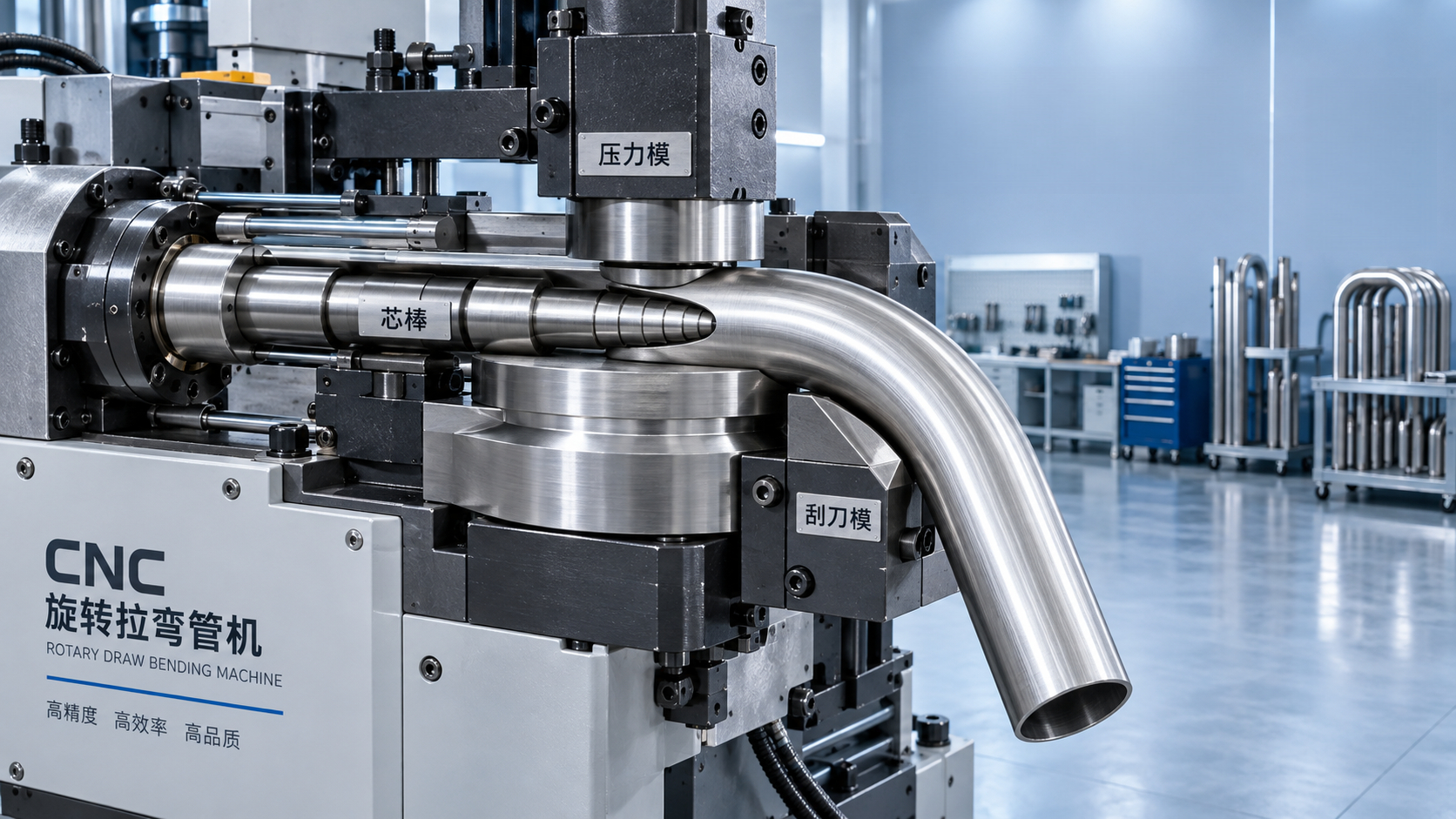
Wrinkling on the inside of a bend is usually a support and material-flow problem, not simply an operator error. When a Pipe bending machine pulls a tube around the bend die, the outside wall is stretched while the inside wall is compressed. If the compressed wall is not supported correctly, excess material has nowhere to go and forms waves or folds.
Thin-wall tubing, small bend radii, large tube diameters, soft materials, and inconsistent tooling setups all make wrinkling more likely. The practical solution is to control the material before it enters the bend, keep it supported during rotation, and avoid asking the tube to form beyond what its wall thickness and radius can tolerate.
Identify where the wrinkle begins
Before changing machine settings, inspect the location and shape of the defect. This often points directly to the cause.
- Wrinkles at the start of the bend often indicate poor clamping, incorrect pressure-die position, or insufficient support as bending begins.
- Wrinkles through the middle of the bend commonly result from inadequate mandrel support, an overly tight radius, or insufficient pressure-die assist.
- Wrinkles near the end of the bend may be caused by premature pressure release, mandrel withdrawal timing, or a tube that is slipping in the clamp.
- One-sided or uneven wrinkling can indicate misaligned tooling, an oval tube, uneven lubrication, or material variation from one batch to another.
A wrinkle that appears in exactly the same place on every part is normally a setup issue. A wrinkle that changes position or severity between parts may point to inconsistent tube dimensions, contamination, changing lubrication, or unstable machine movement.
Start with the tube, not the machine setting
Operators sometimes compensate for poor incoming material by increasing clamp pressure or adding more boost. That can hide the symptom temporarily, but it can also produce flattening, marking, cracking, or unpredictable bend angles. Check the tube first.
Wall thickness must be reasonably consistent around the tube and along its length. A thin section on the inside radius will buckle earlier than the nominal specification suggests. Welded tube also deserves attention: the weld bead should be positioned according to the forming requirement and should not interfere with mandrel insertion or die contact. If the seam is high, hard, or inconsistently located, the tube may move differently through the tooling.
Material condition matters as much as dimensions. Very soft annealed tube may wrinkle more easily under compression, while a harder material may resist compression but crack when stretched. Coated, polished, or stainless tubing can require different lubrication and tooling surface conditions from plain carbon steel. Do not assume that a program which works on one alloy will transfer unchanged to another.
The bend radius is the other basic limit. A tight centerline radius relative to tube diameter and wall thickness puts much more compression into the inside wall. When the design allows it, increasing the bend radius is often the most reliable way to reduce wrinkling. It reduces forming stress without requiring aggressive machine adjustments.
Match the bend die, clamp die, and pressure die to the work
Tooling does more than hold the tube. It controls how the tube is drawn, compressed, and supported throughout the bend. A pipe bending machine cannot produce stable results when die grooves are worn, poorly matched, or incorrectly aligned.
The bend die groove should support the outside diameter without excessive clearance. Too much clearance lets the tube flatten and migrate within the groove. Too little clearance can mark the surface, create drag, or make loading difficult. The groove profile must also suit the tube shape. Round tube, square tube, rectangular tube, and thin-wall decorative profiles do not behave the same way under bending.
The clamp die must grip the tube firmly enough to prevent slipping, but excessive clamping pressure can crush thin-wall material before the bend even starts. If operators keep increasing pressure to stop movement, inspect the clamp surface, tube cleanliness, and die condition. Oil, scale, polishing residue, or damaged serrations can reduce grip and lead to false adjustments.
Pressure-die alignment is especially important for wrinkle control. The pressure die should support the tube closely at the tangent point, where straight material begins to enter the curved section. If the pressure die sits too far away, the tube’s inner wall is free to buckle. If it is set too aggressively, it can increase drag and produce scoring or stretching.
Use pressure assist with restraint
Many rotary-draw setups use pressure-die assist, sometimes called boost, to feed material toward the bend during rotation. Proper boost can reduce thinning on the outside wall and help the tube fill the bend more evenly. Too much boost, however, pushes extra material into the compression zone and can make inside wrinkles worse.
Adjust boost in small increments and inspect both sides of the bend. A setting that improves the outside radius but creates a larger inside ripple is not an improvement. The target is a stable balance: acceptable wall thinning, a smooth inside radius, and no tube movement in the clamp.
When a mandrel and wiper die are necessary
For thin-wall tube or demanding bend radii, external dies alone are often not enough. A mandrel supports the tube internally during bending, while a wiper die prevents the inside wall from folding immediately behind the tangent point. These tools are not optional refinements when the geometry exceeds what unsupported bending can handle.
Mandrel selection depends on tube size, wall thickness, material, and bend severity. A simple plug mandrel may work for moderate bends. Ball mandrels provide support farther into the bend and are commonly used when the tube needs to remain round through a tighter radius. Adding more balls is not automatically better; excessive friction, poor lubrication, or incorrect positioning can create drag and surface damage.
Mandrel position is critical. If it sits too far back from the tangent point, the tube begins to collapse before internal support reaches the vulnerable area. If it is too far forward, it may restrict material flow, leave marks, or complicate extraction. The correct position is determined by the tool design and then refined through controlled trial bends.
A wiper die works at the inside tangent, where a wrinkle often first develops. Its thin edge must meet the tube accurately and remain in sound condition. A damaged, blunt, or improperly fitted wiper die will not stop buckling. Operators should also avoid treating a wiper die as a cure for every defect. It cannot compensate for an unsuitable bend radius, a badly fitted mandrel, or a pressure die that is not supporting the tube.
Lubrication affects wrinkle control as well as tool life
Lubrication is often discussed as a way to prevent galling, but its effect on material flow is equally important. The tube needs controlled movement through the pressure die, around the bend die, and over the mandrel. Dry contact creates drag. Uneven lubrication creates uneven drag, which can cause one side of the bend to behave differently from the other.
Use a lubricant appropriate for the material and process, and apply it consistently where the tooling requires it. Mandrel lubrication is particularly important because the tube must slide over internal support while being compressed around the bend. Excess lubricant on clamp surfaces can reduce holding force, so keep the clamping zone clean unless the tooling instructions specify otherwise.
When wrinkles appear after a lubricant change, do not immediately alter every machine parameter. Compare the new lubricant’s coverage and behavior under forming pressure, then make one controlled adjustment at a time.
Set the process in a sequence that reveals the real cause
Changing clamp pressure, pressure assist, mandrel position, speed, and lubrication all at once makes it difficult to learn what fixed the problem. A disciplined setup sequence is faster in the long run and makes repeat production more reliable.
- Confirm the tube material, outside diameter, wall thickness, seam condition, and required bend radius.
- Inspect the bend die, clamp die, pressure die, mandrel, and wiper die for wear, damage, contamination, and correct fit.
- Set tool alignment and clamp pressure before adding more boost or increasing machine force.
- Position the mandrel and wiper die according to the tooling arrangement, then make a low-speed trial bend.
- Adjust pressure-die assist gradually while checking the inside radius, outside thinning, flattening, and bend angle together.
- Record the final settings with the tube specification and tool set, not merely with a part number.
Slower bending can help when machine motion is unstable or lubrication is marginal, but speed reduction alone does not solve a structural support problem. If a tube wrinkles at low speed with correct loading, the focus should return to radius, tooling, mandrel support, and material condition.
Do not confuse wrinkling with other bend defects
This distinction matters because adding a wiper die to solve outside cracking, or increasing boost to solve die scratches, can create a second problem without correcting the first one.
Choose the bending method for the section you are forming
A rotary-draw pipe bending machine is generally the appropriate choice when round tube needs a controlled, repeatable bend with a specified radius. It is particularly useful where shape retention and consistent orientation matter. For large-radius rings, channels, angle steel, flat bar, or asymmetric structural sections, a profile rolling machine may be more suitable than trying to force the work through tube-bending tooling.
For example, a Profile bender with adjustable lateral guide rolls and distortion-correction support is relevant when forming profiles, circular flanges, or double-curved workpieces. Its straight-line adjustable roller arrangement is intended to limit cross-sectional deformation during rolling. That is a different forming process from rotary draw bending, so it should be selected because the workpiece and required geometry suit rolling, not simply because a tube has shown wrinkles.
Trying to use the wrong machine type is a common source of repeated quality problems. Before changing dies or programs, confirm whether the part is a tight, localized tube bend or a broad-radius rolled profile. The correct process choice can eliminate the root cause of deformation that adjustment alone cannot overcome.
Build a repeatable inspection routine
Once the bend looks acceptable, inspect more than the visible wrinkle. Check bend angle after springback, outside diameter or profile shape in the bend, flattening, surface condition, and the start and end positions of the bend. A smooth-looking part can still fail later assembly if the tube has ovalized or drifted from its required orientation.
Keep a first-off sample from each stable setup where practical. It gives operators a direct comparison when material, tooling, or machine behavior changes. For repeated production, document the die set, mandrel type, wiper configuration, lubrication method, clamp setting, pressure assist, bending speed, and material specification. That record turns troubleshooting from guesswork into controlled correction.
The most effective way to prevent wrinkles is to treat them as evidence of uncontrolled compression. Confirm that the tube is suitable for the requested radius, support the inside wall where it needs support, maintain clean and correctly aligned tooling, and change one variable at a time. A smooth bend comes from balanced material flow, not from applying more force to the machine.
search
Products Navigation
Send Us A Message