




How much payload margin does a high payload handling robot arm need?
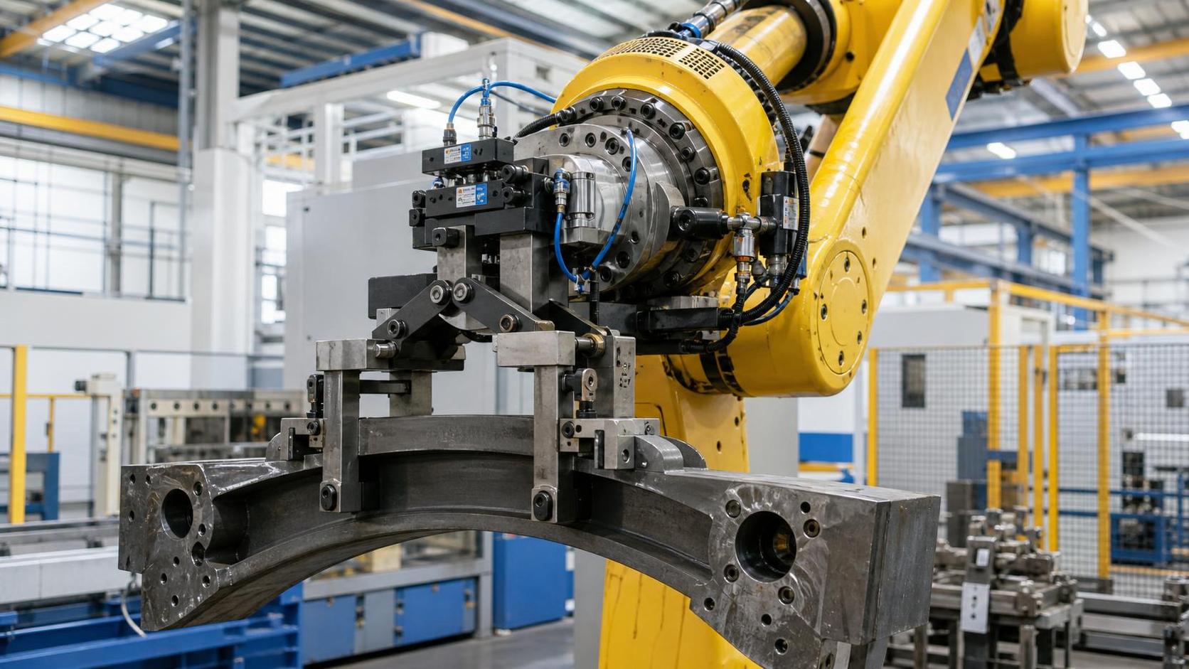
For quality control and safety managers, selecting a high payload handling robot arm is not simply a matter of comparing the part weight with the robot’s maximum rated payload. The real question is whether the robot retains enough capacity to move safely, repeatedly, and accurately when the complete production condition is considered.
A robot may appear adequately sized on paper because the workpiece weighs 80 kg and the robot is rated for 100 kg. Yet the actual load at the wrist may include a 15 kg gripper, pneumatic valves, protective guards, sensor brackets, cable dress packs, and a changing center of gravity. Add fast acceleration, extended reach, or a demanding duty cycle, and a seemingly acceptable selection can become a source of overload alarms, poor placement accuracy, accelerated gearbox wear, or an avoidable safety concern.
Payload margin is therefore a practical risk-control tool. It gives the automation team room for real-world variation rather than asking the robot to work continuously at its theoretical limit.
Payload rating is a starting point, not the selection result
Every industrial robot has a published payload rating, usually expressed as the maximum mass that can be carried at the wrist under specified conditions. That figure is important, but it does not mean that every load below that number will behave equally well.
Robot manufacturers normally define payload performance together with limits for wrist moment, wrist inertia, center-of-gravity position, axis speed, and robot posture. A 100 kg robot carrying a compact 90 kg load close to the mounting flange may perform very differently from the same robot carrying a long, offset 90 kg fixture. In the second case, the robot’s wrist and arm joints experience much greater torque during movement.
For a high payload handling robot arm, the load assessment should include:
- The maximum workpiece weight, including normal material tolerances and retained scrap or process residue.
- End-of-arm tooling weight, including grippers, vacuum cups, magnets, clamps, sensors, adapters, and protective covers.
- Hoses, cables, pneumatic manifolds, and dress-pack components supported by the robot.
- The distance between the robot flange and the combined center of gravity.
- Payload inertia, especially for long plates, welded frames, pipes, coils, and asymmetric fabricated parts.
- Acceleration, deceleration, reach, orientation changes, cycle time, and operating temperature.
Ignoring any one of these elements can produce a misleading payload calculation. For safety managers, the key concern is not whether the robot can complete one slow lift during commissioning. It is whether it can repeatedly execute the intended path without approaching mechanical, electrical, or control-system limits.
What payload margin should be allowed?
There is no single percentage that is correct for every automation project. A sensible margin depends on how predictable the load is, how severe the motion is, and how costly an interruption would be. Still, the following guide is useful during early selection.
These are planning ranges, not a substitute for the robot manufacturer’s load chart and simulation tools. If a cell handles a 70 kg fabricated component with a 20 kg gripper assembly, choosing a 100 kg robot may look reasonable from a mass perspective. But if the tooling projects far from the flange, the part is lifted at speed, or the robot reaches across a wide machine opening, a 120 kg or 150 kg class robot may be the safer engineering choice.
In other words, margin should be measured against the fully equipped and moving system, not against the bare part.
The calculation should begin at the robot flange
A useful internal review starts with a simple total payload register. List every item mounted beyond the robot wrist, then use the heaviest realistic combination rather than the nominal or average condition.
Total carried mass = workpiece + end effector + adapters + sensors + valves + cable/hose-supported mass + foreseeable additions.
That last item is frequently overlooked. A robot cell is rarely frozen in its original configuration. A quality team may later request a vision camera, a part-presence sensor, stronger clamp fingers, an inspection probe, or additional guarding around sharp edges. Each change may be small by itself, but together they can consume the margin that made the cell reliable.
Mass is only the first checkpoint. The robot supplier should then verify the payload center of gravity and inertia values using the actual dimensions of the gripper and part. A wide sheet-metal blank, for example, may be relatively light for its size but create significant inertia when rotated. A heavy casting may have an uneven center of gravity because of ribs, flanges, or machined features. Neither condition is well represented by a simple kilograms-only comparison.
Why center of gravity changes the safety decision
Consider holding a load close to your chest versus holding the same load with straight arms. The weight has not changed, but the effort on your body has. A robot experiences the same principle through joint torque and wrist moment.
When the combined center of gravity moves farther from the robot flange, the load creates a larger bending moment. This is especially relevant when the robot handles:
- Large steel plates or curved shells.
- Long pipe sections, beams, and structural components.
- Fabricated assemblies that are loaded off-center.
- Tooling with extended fingers or multiple vacuum zones.
- Parts that must be presented vertically, tilted, or rotated during transfer.
Quality risks can emerge before a formal overload fault occurs. The robot may show greater path deviation under dynamic load, less consistent insertion into a fixture, or variable placement onto a conveyor, weld positioner, or machine table. These issues can look like fixture or programming problems when the root cause is actually an undersized payload envelope.
A safe selection process should therefore require the integrator to provide the calculated center of gravity, moments, and inertias for each relevant pick condition. If one gripper handles several part families, assess the worst condition for each axis—not merely the heaviest item.
Acceleration can quietly erase a comfortable-looking margin
Payload is static; production is dynamic. The moment a robot accelerates, brakes, reverses direction, or rotates a long load, forces rise above the simple gravitational load. High-speed handling cells are particularly exposed because cycle-time pressure often leads to faster motion profiles after installation.
It is tempting to select a robot that meets today’s cycle time at a conservative speed and assume that later optimization will be easy. But a robot operating close to its payload or inertia limits may have little room for improvement. The result can be frequent protective stops, reduced programmed speed, or a compromise between throughput and equipment life.
For safety review, ask the following questions:
- Will the robot travel at maximum reach while carrying the heaviest part?
- Does the cycle include abrupt stops, 180-degree turns, or high-speed wrist rotation?
- Can parts swing, flex, or shift inside the gripper?
- Are emergency-stop conditions and controlled stops evaluated with the actual payload?
- Will the production team later request a shorter cycle time?
A robot that is lightly loaded during slow teaching can behave quite differently in automatic production at full programmed speed. This is why commissioning should include representative production loads, not only empty-tool path checks.
Build the margin around the process, not around a catalogue number
Material handling in metal fabrication offers a good example. A cell may load thick plate blanks into a forming machine, remove rolled cylindrical sections, or transfer conical shells to welding and inspection stations. The part dimensions, edge condition, and grip orientation may vary considerably between jobs. In this environment, a generous payload margin supports more than lifting strength: it supports stable clamping, repeatable positioning, and a safer response to expected production variation.
For operations producing cylindrical, conical, or arc-shaped components from heavier plate, the downstream handling plan should be considered alongside the forming equipment. A CNC Bending machine with 4 roller can improve dimensional control through its four-roller arrangement and reduced lower-roll span, particularly for demanding metal fabrication work. However, better formed-part accuracy also raises the importance of careful robotic handling. If a finished shell is distorted, scratched, or placed inconsistently after rolling, the benefit of accurate forming can be lost downstream.
When evaluating a robot for this kind of cell, record the maximum plate thickness and final component geometry, not only the starting blank weight. A rolled part can present a different center of gravity and gripping surface than a flat sheet. Sharp edges, warm surfaces, oil, scale, and changing diameters may also influence the design and mass of the end effector.
A practical approval checklist for QC and safety teams
Before approving a high payload handling robot arm, quality and safety stakeholders should request evidence that the proposed design has been evaluated in its real operating envelope. The review does not need to become an exercise in robot programming, but it should be specific enough to expose assumptions.
- Confirm the worst-case payload. Use maximum part weight plus complete tooling, not average material weight or a preliminary gripper concept.
- Review load data at the flange. Check center of gravity, wrist moments, and inertia against the robot supplier’s permitted values.
- Check the full reach envelope. A load may be acceptable near the robot base but become restrictive at extended reach or overhead positions.
- Validate the intended cycle. Simulate or test the actual acceleration, orientation changes, handoff points, and cycle rate.
- Include abnormal but foreseeable conditions. Consider a wet or oily part, a slightly oversized workpiece, an added sensor, a missed placement, and recovery after a stop.
- Verify end-effector retention. Payload capacity does not prove that vacuum, magnetic, or mechanical gripping is secure during all motions.
- Document future allowance. Identify what portion of the margin is reserved for planned tooling changes, additional inspection devices, or new product variants.
This checklist is valuable because it turns “capacity” into traceable engineering evidence. It also gives quality managers a clearer basis for approving process capability and gives safety managers confidence that operating limits are not being treated as targets.
Common selection mistakes that create later problems
One common error is selecting according to the heaviest workpiece alone. Another is using the gripper supplier’s estimated weight before cables, valves, adapters, and guarding are finalized. Both approaches can leave a cell with only a few kilograms of apparent spare capacity—far too little once actual production details arrive.
Another mistake is treating all 100 kg-rated robots as interchangeable. Reach, arm geometry, allowable inertia, wrist configuration, and motion performance differ by model. One robot may be well suited to compact palletizing while another handles offset fabrication parts more comfortably. The correct question is not “Which robot has the required payload?” but “Which robot can carry this complete load through this exact motion with acceptable margin?”
Finally, do not confuse a large payload rating with a complete safety solution. Safe automation also depends on risk assessment, safeguarding, safe speed and separation functions where applicable, gripper failure behavior, part-drop prevention, emergency-stop performance, and operator access during loading, inspection, and recovery.
The decision rule: leave room for reality
A well-chosen robot arm should not spend normal production living at the edge of its ratings. If the calculated total payload is close to the robot’s maximum capacity, or if the center of gravity and inertia are difficult to control, moving to the next payload class is often the more responsible decision. The extra capacity can protect repeatability, simplify future tooling changes, and reduce pressure to slow the process after installation.
For most quality control and safety managers, the right payload margin is the one supported by documented load data, realistic motion validation, and a clear allowance for variation. Select the robot based on the heaviest complete tool-and-part combination, verify moments and inertia at the worst reach, then retain enough headroom for the production changes that almost always follow. That approach makes a high payload handling robot arm a dependable part of the manufacturing system rather than its next hidden constraint.
search
Products Navigation
Send Us A Message