




What frame loads require a heavy duty handling robot arm?
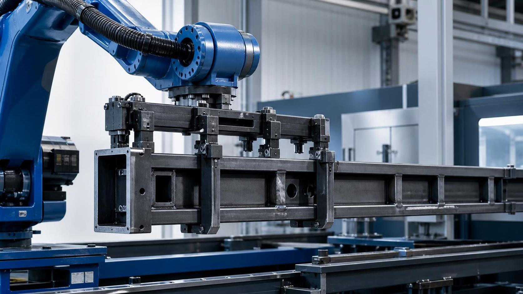
A heavy duty handling robot arm is required when the frame load exceeds the useful payload, wrist moment, reach stability, or dynamic capacity of a standard robot. Frame weight alone is an incomplete selection criterion. A welded machine base, structural frame, H-beam assembly, or fabricated enclosure may be within a robot's nominal payload rating while still producing excessive torque at the wrist or base because its center of gravity is far from the flange.
The practical threshold is reached when the robot must repeatedly lift, rotate, transfer, or accurately position a frame whose mass, geometry, gripping method, and motion profile create loads beyond the rated operating envelope. This commonly occurs with long welded structures, off-center assemblies, rigid machine beds, steel frames carrying fixtures, and fabricated components that must remain stable during welding, machining, inspection, or transfer.
Payload Is Only the Starting Point
Robot payload ratings are generally stated for a defined load condition near the wrist flange. A frame is rarely a compact, centered load. The robot must carry the workpiece, gripper, mounting plate, sensors, cabling, protective covers, and sometimes a compliance device or rotary tool. The total moving mass, rather than the frame mass by itself, is the first value to establish.
For example, a robot lifting a 600 kg welded frame with a 120 kg mechanical gripper is not handling a 600 kg payload. The wrist carries at least 720 kg before allowing for brackets, hoses, connectors, or tooling retained during the cycle. Selecting a robot whose nominal rating merely equals the calculated static mass leaves little usable margin for acceleration, braking, product variation, or loss of grip caused by surface condition.
Heavy-duty selection becomes appropriate when payload use is close to the robot's continuous operating limit, particularly where the frame must be accelerated rapidly or held horizontally at full reach. A larger robot class may provide greater structural stiffness and a more suitable inertia range, even when the nominal payload difference appears unnecessary on a simple weight comparison.
Center of Gravity Often Decides the Robot Class
A long frame creates leverage. The relevant relationship is the load mass multiplied by the horizontal distance from the robot wrist to the frame's center of gravity. Increasing that distance raises wrist torque, shoulder loading, and the tendency for the arm to deflect during starts and stops. A light but long rectangular weldment can therefore require a heavier robot than a denser, compact casting of similar mass.
Center of gravity data should describe three directions from the robot flange, not simply a single distance. Frames are frequently asymmetric because gussets, machined pads, brackets, cable trays, or attached components shift mass away from the geometric center. If a gripper picks the frame from one rail or one edge, its own mass and offset can create a load case substantially different from the drawing's nominal balance point.
The most demanding posture is often not the pick point. It may occur when the robot extends the frame over a conveyor, rotates it from vertical to horizontal, reaches into a fixture, or withdraws from a machine enclosure. Each posture changes joint loading. A load chart that is acceptable at a short reach may be unsuitable after the same frame is moved farther from the robot base.
Long Frames and H-Beams
H-beams and fabricated frames introduce a second problem: bending and oscillation. The robot may safely support the calculated weight while the workpiece itself deflects between gripping points. When motion starts, that deflection can become a swinging load. The robot then sees changing inertia, the gripper experiences uneven force, and placement repeatability falls.
Long structural members are often better handled with two coordinated robots, a robot and a servo positioner, or a purpose-designed end effector with multiple support points. The choice depends on length, stiffness, transfer path, and the accuracy required at the destination. A single heavy duty handling robot arm can be appropriate for a rigid frame with a controlled center of gravity, but adding payload capacity does not automatically solve workpiece flexing.
Static Weight and Dynamic Load Are Different Calculations
A stationary robot holding a frame sees a static gravitational load. A production cycle adds acceleration, deceleration, direction reversal, and wrist rotation. These forces are especially significant when a frame is moved between welding stations, turned for access to another face, or inserted into a precision fixture.
High speed is not the only source of dynamic loading. A slow but abrupt stop can create a larger disturbance than a faster, smoothly blended path. Inertia rises sharply when mass is distributed far from the rotation axis. A broad welded cabinet frame, for instance, can impose demanding rotational inertia even if its total weight is modest relative to the robot's rated payload.
The correct evaluation uses the robot supplier's payload, center-of-gravity, and inertia limits together. Payload software or a load calculation tool should model the actual gripper and frame. It should also include the intended speed and orientation range. A static lifting demonstration is useful for proving grip, but it does not validate the full production motion.
Frames That Commonly Justify Heavy-Duty Robotic Handling
Heavy-duty arms are typically justified for welded machine bases, large fabricated skids, heavy steel doors, H-beam subassemblies, construction-equipment frames, presses or machine housings, and fixtures that remain attached during transfer. These loads tend to combine substantial mass with inconvenient geometry. Their value also increases the need for controlled handling, because contact damage or distorted locating surfaces can create downstream assembly problems.
Frames leaving a welding cell often require rotation for inspection, grinding, machining, or access to the opposite side. If the frame is manually repositioned with lifting equipment, the robot alternative must be judged against the complete sequence: pickup, orientation change, fixture clearance, controlled set-down, and release. A robot that can lift the frame but cannot rotate it through the required path without crossing a joint limit is not a viable handling solution.
Surface condition matters at this stage. Laser-cut, plasma-cut, flame-cut, sheared, or stamped plate components can carry burrs and slag before they are assembled into a frame. Burrs at gripper contact locations create false seating and local point loading. When sheet components are prepared before assembly, equipment such as the RNS 800 Sheet metal deburring machine can remove edge and hole burrs from metal sheets within its 800 mm processing width and 0.5-40 mm thickness range. This does not determine robot capacity, but it can improve the consistency of contact faces used by nests, clamps, and end-effectors.
Gripper Mass, Grip Security, and Load Path
The end effector is part of the handling system, not an accessory to be estimated later. Magnetic lifters, vacuum systems, mechanical clamps, fork-style tools, and custom pin fixtures each change the effective payload and center of gravity. The load path from frame to gripper must remain secure through every orientation. A gripper that is adequate for vertical lifting may be unsuitable when the frame is inverted or accelerated sideways.
Vacuum gripping deserves particular caution on welded or rough steel frames. Surface scale, weld spatter, porosity, uneven plate, and small gaps can reduce seal integrity. Vacuum tools also require a defined response to pressure loss and a retained-load condition where appropriate. Mechanical clamping can tolerate rougher surfaces, but it adds weight and may interfere with weld beads, machined faces, or component openings.
For thin-wall frames, gripping force must be evaluated against local deformation. Increasing clamp force to prevent slipping can distort a rail or panel. Supporting the frame at multiple structural nodes is often more effective than applying greater force at one convenient location. The same principle applies to fork tools: fork spacing and insertion depth influence bending in the frame as well as the stability of the robot load.
Reach, Mounting Position, and Foundation Load
Heavy frames make robot placement a structural decision. Locating the robot farther from the machine or fixture increases reach and therefore joint torque. Moving the robot closer may reduce load demand but leave insufficient clearance for the frame to rotate. The preferred arrangement keeps the highest-load positions near the robot's stronger working zone while preserving a collision-free path for the longest dimension of the frame.
Mounting height also changes the problem. A pedestal can improve access over conveyors or fixture walls, yet it raises the effect of inertial forces on the support structure. Floor-mounted bases, elevated steel structures, tracks, and overhead arrangements each need a documented reaction-load assessment. The robot foundation must resist the combined forces from the arm, workpiece, emergency stop events, and repeated directional changes without settling or vibration.
Floor flatness alone is not evidence of adequate support. Anchor layout, concrete thickness, reinforcement, nearby trenches, and the stiffness of a fabricated pedestal affect stability. A large robot may maintain repeatable joint position while the base structure moves slightly under load, causing errors at the gripper. This is particularly visible when placing a frame onto pins, into a machining fixture, or against locating stops.
Cycle Demands Can Turn a Borderline Load into a Heavy-Duty Application
A frame handled once per shift can tolerate conservative motion and longer settling time. The same frame moved repeatedly through welding, inspection, and finishing requires capacity for continuous duty. Heat from nearby welding, abrasive dust, coolant mist, and weld spatter may also influence cable routing, protective measures, and maintenance intervals, although they do not change the robot's rated payload.
Repeated rotation is a frequent source of poor initial sizing. A robot may lift a frame vertically with ample reserve, then struggle when the same frame must be rotated around an offset axis. The control system can reduce speed to remain within limits, but that may disrupt the required takt time. Selecting a heavy-duty arm early is often more practical than attempting to recover cycle time later through aggressive acceleration settings.
Load variation must be documented across the production mix. A bare welded frame, a frame carrying brackets, and a frame with temporary assembly tooling are separate load cases. The heaviest configuration is not always the most restrictive one; a lighter configuration with a greater offset can create the largest wrist moment. Programs should be linked to verified part and gripper data rather than assuming that similar-looking frames share the same allowable motion.
Recognizing When a Standard Robot Is Being Forced Beyond Its Role
Several signs point to an undersized or poorly matched handling system: reduced speed near full reach, repeated overload warnings, visible frame sway after stopping, difficulty meeting placement tolerance, or an end effector that consumes an excessive share of the payload rating. These symptoms can also originate from weak fixturing, inaccurate center-of-gravity data, or an unstable base. Replacing the robot without identifying the actual cause can leave the same failure mode in place.
There is a meaningful difference between a robot limited by mass and one limited by inertia. Mass problems appear in lifting and extended-arm postures. Inertia problems often emerge during rotation, reversal, or emergency deceleration. A frame can pass a vertical pickup test yet exceed the permitted inertia envelope when turned on a wrist axis. Both conditions should be checked before fixture design is finalized.
Where the part geometry is highly variable, a controlled lifting fixture or positioner may be preferable to a robot-only solution. The robot can then perform transfer or loading while the fixture carries the demanding rotational work. Conversely, when the frame must travel between several stations with different orientations, a heavy duty handling robot arm offers greater path flexibility than a fixed lifting arrangement, provided the reach and load envelope remain valid throughout the route.
Data Needed Before Selecting Capacity
A reliable specification begins with a drawing or measured model of the frame in every handled condition. Record the bare frame mass, attached components, temporary tooling, expected center of gravity, outer dimensions, and permitted gripping zones. Include the end-effector mass and its center of gravity relative to the robot flange. For frames with uncertain internal material distribution, a controlled weighing and balance test is more useful than relying only on nominal fabrication drawings.
- Define the highest and lowest mass configurations, including handling fixtures retained during the cycle.
- Map every required orientation, especially horizontal carry positions and full rotations around an offset centerline.
- Establish the transfer path with actual fixture walls, machine doors, conveyors, and safety boundaries present in the model.
- Identify whether the frame is rigid enough for one pickup point or requires distributed support to avoid deflection.
- Evaluate stopping behavior and recovery after an interrupted cycle, because a suspended heavy frame cannot always be returned along the normal path.
The result should be a load envelope rather than a single payload number. When that envelope approaches the limit in mass, moment, inertia, reach, or duty cycle, the application has entered heavy-duty handling territory. Selecting capacity from the complete envelope protects motion quality and fixture accuracy while leaving a realistic operating margin for the frames that production will actually deliver.
search
Products Navigation
Send Us A Message