




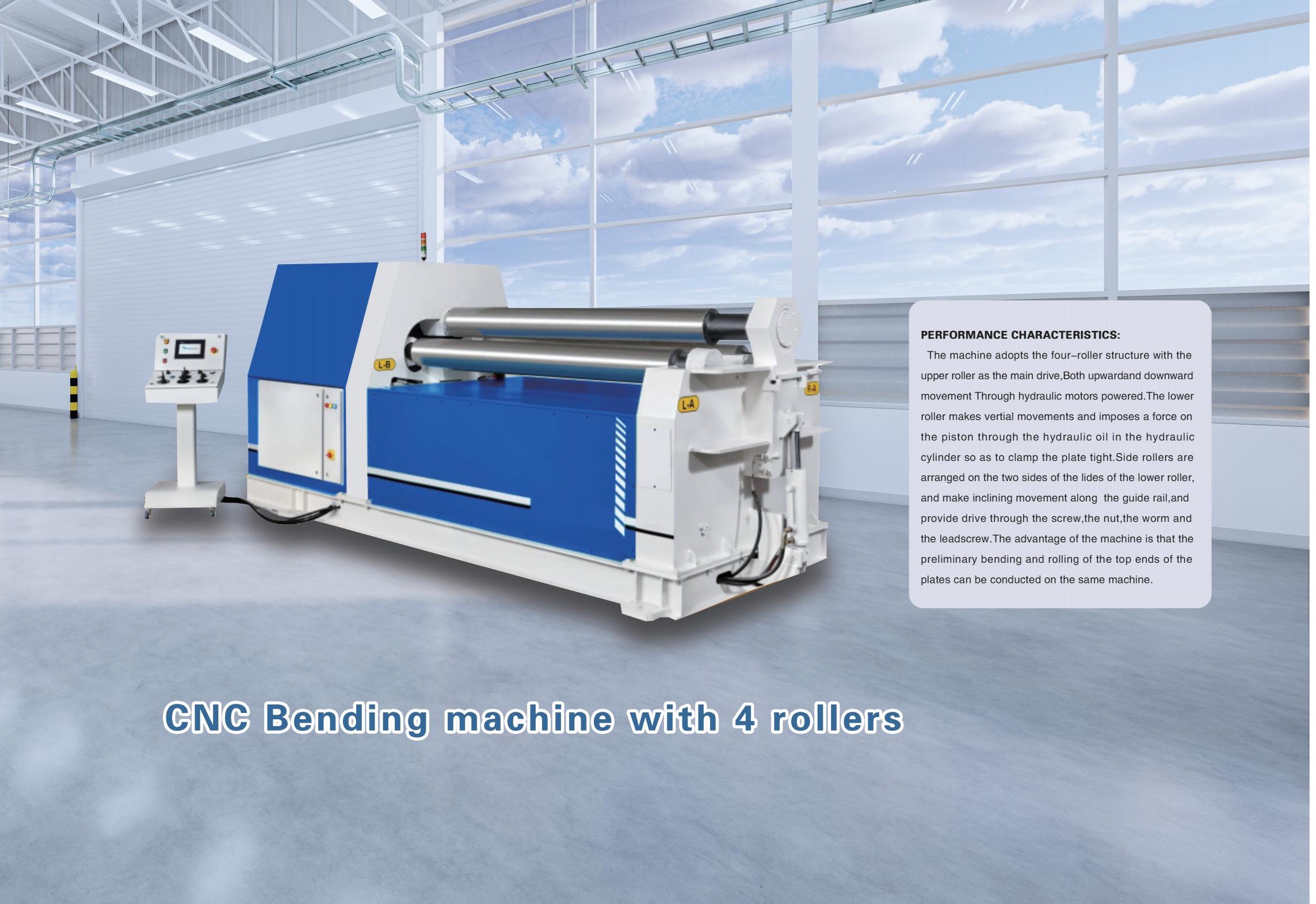
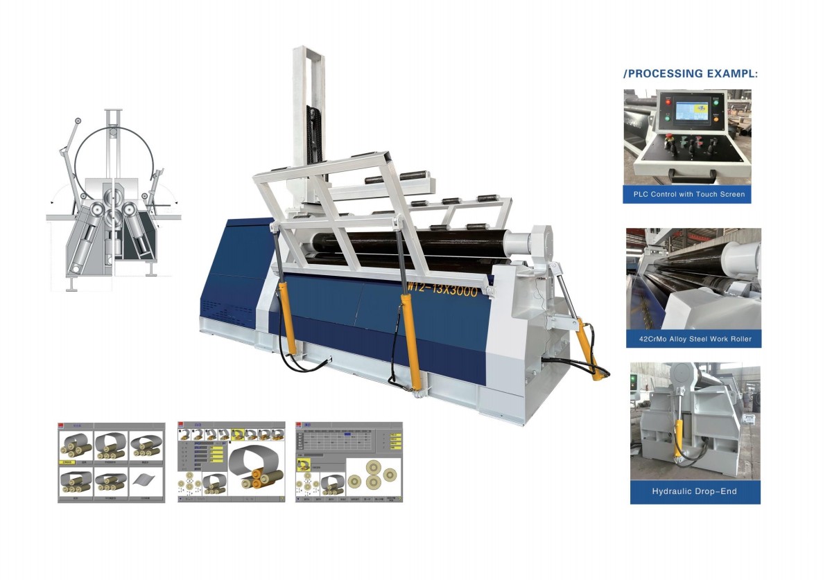
CNC Bending machine with 4 roller
Full-range Machinery & Customized Non-standard Solutions
Authorized Certificates & Independent R&D Patents
Over 10 Years Global Export & Worldwide Project Cases
Navigation

CNC Bending machine with 4 roller Description
1. Introduction to the 4-Roller CNC Bending Machine
A roll bending machine is a forming device that uses rotating working rollers to progressively bend sheet metal into desired profiles. Capable of producing cylindrical, conical, and arc-shaped components, it is an essential piece of equipment in modern metal fabrication. The forming process relies on hydraulic or mechanical force to actuate the working rollers, whose coordinated movements—through rotation and positional adjustment—enable the production of a wide variety of curved geometries.
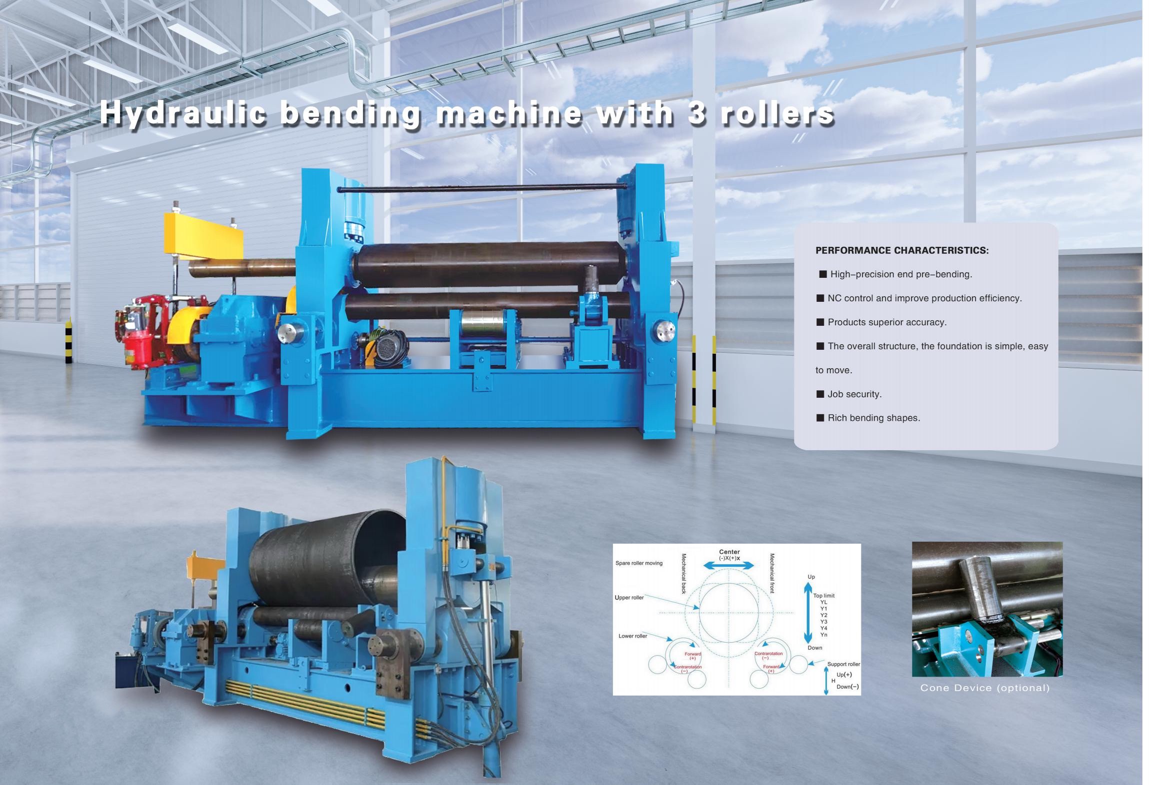
In a conventional symmetrical three-roller plate bending machine, the upper roller is vertically actuated by hydraulic cylinders positioned symmetrically above the two lower rollers. Driven by the final-stage gearing of the main reducer, the upper roller rotates in unison with the two lower rollers, delivering the torque required for rolling. As a uniform metal plate passes between the three rollers, the downward pressure from the upper roller, combined with the rotational motion of the lower rollers, induces continuous bending. This results in permanent plastic deformation, characterized by compressive strain on the inner surface, neutral strain in the middle, and tensile strain on the outer surface. The plate is thereby formed into cylinders, cones, or segmented curvatures.
However, a notable limitation of this hydraulic three-roller design is that the leading and trailing ends of the sheet cannot be fully formed and must be pre-bent using auxiliary equipment. Consequently, this configuration is primarily suited for heavy-duty applications involving plate thicknesses of 50 mm or greater. To address these constraints, the 4-roller CNC bending machine incorporates an additional row of fixed idler rollers beneath the two lower rollers. This design shortens the span between the lower rollers, significantly enhancing the dimensional accuracy of the finished workpiece and improving overall machine rigidity and performance—making it a superior solution for precision bending applications.
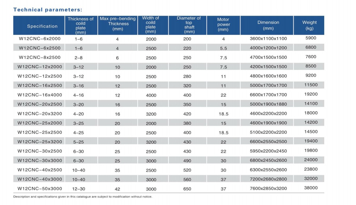
2.Technical parameter for CNC Bending machine with 4 roller
3.Characters for CNC Bending machine with 4 roller:
Plate bending machines can be divided into mechanical and hydraulic types based on their drive methods.
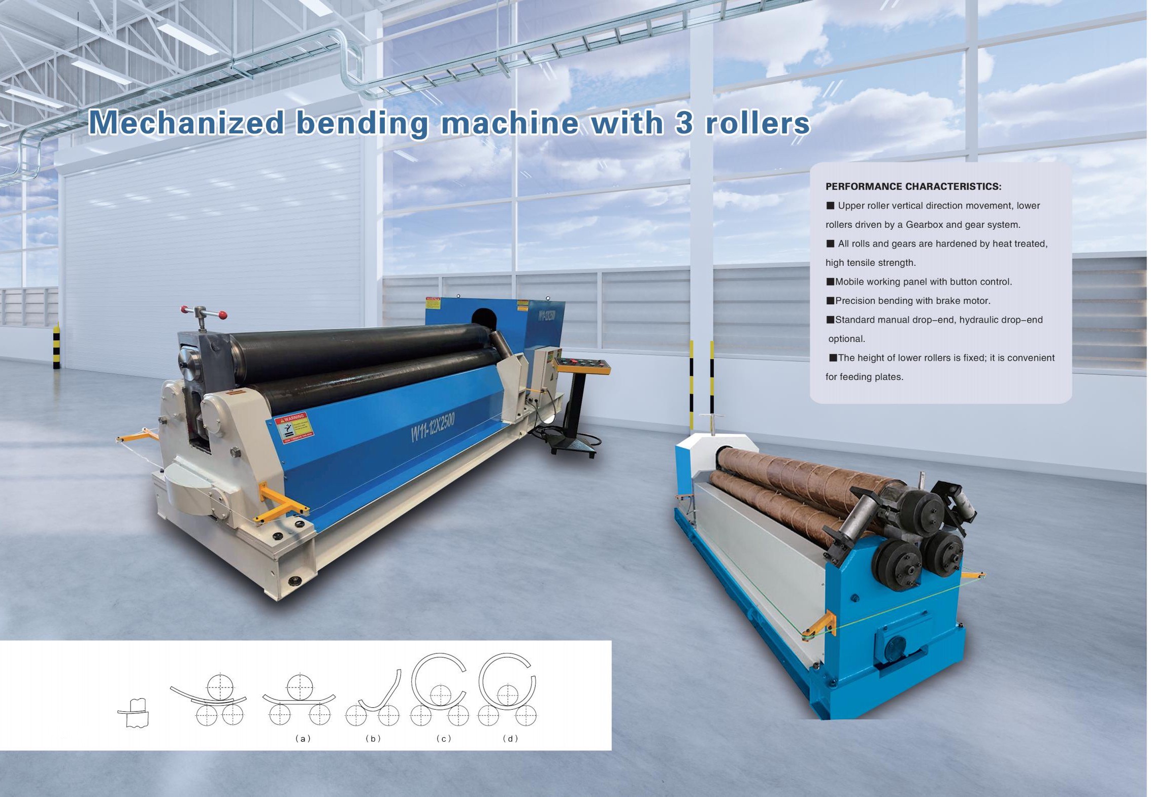
The most common structural form is the three-roller symmetrical design. In this configuration, the upper roller moves vertically up and down at the symmetrical position between the two lower rollers, driven by a worm gear and worm wheel transmission. The two lower rollers rotate through the meshing of the reducer output gear with the lower roller gears, which in turn drives the plate forward.
In hydraulic-type machines, the working principle is as follows: an electric oil pump delivers high-pressure oil through high-pressure pipes to the working cylinder or hydraulic motor. The high-pressure oil pushes the piston inside the cylinder or the motor rotor, generating thrust and torque, which then drive the mold components to bend the profile. The core forming principle is based on the "three points define a circle" concept. By changing the relative position of the workpiece and utilizing rotational motion, the plate undergoes continuous plastic deformation. When the downward pressure exerted by the upper roller exceeds the material's yield limit, permanent bending deformation occurs.
The basic rolling procedure is: feed the plate into the gap between the upper and lower rollers and make the necessary adjustments, then start the main motor. Through repeated pressing and forward/reverse rotations, the rolling process is gradually completed.
The equipment's transmission system consists of two parts: the main drive and the auxiliary drive. The main drive system uses a motor to power the reducer and gear pairs, which rotate the lower rollers. The auxiliary drive system—responsible for raising and lowering the upper roller—uses a separate motor to drive the worm wheel, worm gear, and screw mechanism.
The lubrication system typically employs manual application or centralized lubrication methods. Regular maintenance is essential to ensure the equipment operates smoothly, extend its service life, and maintain consistent forming accuracy.
products faq
A 3-roller machine uses three rollers arranged in a pyramid or asymmetric configuration. It is simpler, more economical, and suitable for general fabrication. However, it typically requires the plate ends to be pre-bent separately or leaves a flat section on each end. A 4-roller machine adds a fourth (pinching) roller that securely clamps the plate edge, enabling pre-bending and rolling in a single pass with no flat ends—resulting in higher precision, faster operation, and less material waste, making it ideal for high-volume and precision work.
The machine can process a wide range of materials including carbon steel, stainless steel, aluminum, copper, and alloy plates. Thickness capacity varies by model: light-duty machines handle 2–12mm, medium-duty 12–40mm, and heavy-duty models can roll plates up to 120mm (or even 400mm on special configurations). Maximum width typically ranges from 1,000mm to 16,000mm. Capacity depends on material yield strength—higher strength steels require more force for the same thickness.
Yes. Many plate rolling machines support conical rolling. By adjusting the angle of the rollers relative to the plate feed, the machine can taper the curvature—forming truncated cones, tapered wind tower sections, and other conical shapes. This is achieved by angling the rollers or feeding the plate at a controlled angle relative to the roller axis.
Pre-bending is the process of bending the leading and trailing edges of the plate before full rolling. This ensures the plate ends form a continuous curve matching the rest of the cylinder—eliminating the flat sections that would otherwise need to be cut off or welded later. 4-roller machines perform pre-bending automatically in the same setup, while 3-roller machines may require a separate pre-bending attachment or a press brake. Proper pre-bending is critical for achieving full roundness and dimensional accuracy of the finished cylinder.