




How to Identify and Fix Common Laser Cutting Defects in Sheet Metal Production
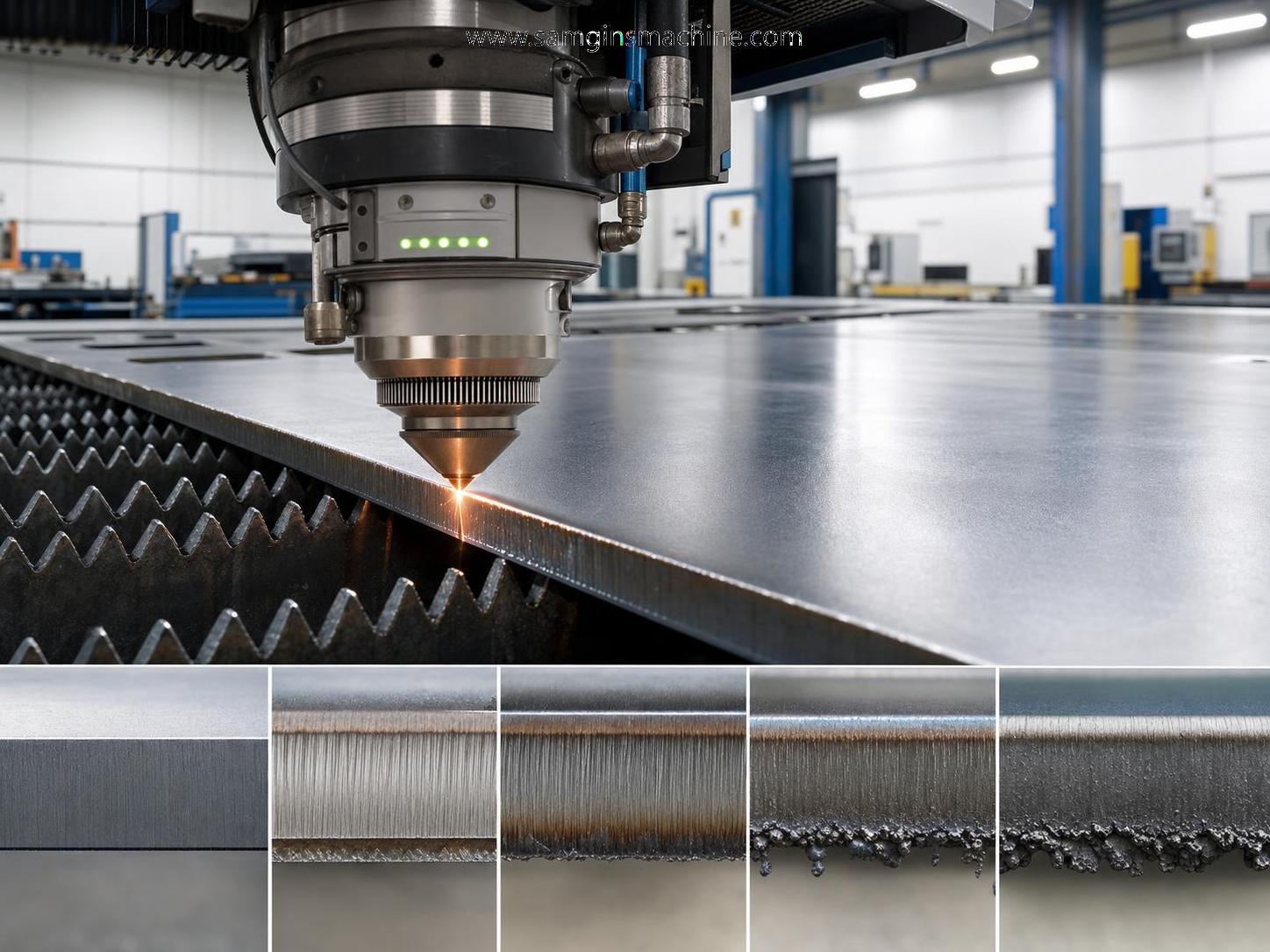
How to Identify and Fix Common Laser Cutting Defects in Sheet Metal Production
Laser cutting defects can quickly reduce sheet metal quality, slow production, and increase material waste if operators do not identify the root cause in time. In modern metal fabrication, understanding common defect types and knowing how to correct them is essential for stable output and lower costs. This guide will help users and machine operators recognize typical laser cutting problems, analyze their causes, and apply practical solutions to improve cutting accuracy, edge quality, and overall production efficiency.
If you spend enough time around sheet metal production, you learn that most laser cutting defects do not come from one dramatic machine failure. They usually start with a small mismatch: nozzle condition, gas pressure, focus position, dirty optics, unstable material, or a cutting library that was never adjusted for the actual plate on the table. Operators who catch these signs early save far more time than those who keep recutting parts and arguing with the drawing.
The practical way to troubleshoot is simple: look at the cut edge, look at the bottom side, check whether the defect is consistent across the sheet, and then verify settings in an order that makes sense. Do not change five parameters at once. That only hides the real cause.
Start with the edge, not the screen
Before touching the HMI, inspect a few failed parts by eye and by hand. The edge usually tells you more than the parameter page.
- Heavy dross attached to the bottom edge usually points to speed, focus, gas flow, or nozzle issues.
- A rough, striated surface with drag lines often suggests power and speed are out of balance, or the beam quality has degraded.
- Burn marks and a wide kerf often show excessive heat input, poor gas purity, or wrong focus height.
- Tapered cuts, where the top opening is wider than the bottom, can mean the focus is off or the nozzle is damaged.
- Incomplete piercing or random uncut sections often come back to plate surface condition, unstable assist gas, or poor nesting strategy around heat buildup.
One useful shop-floor habit: compare bad parts from the center of the sheet and the outer area. If the defect only appears in one zone, check flatness, support condition, and whether the sheet lifts during cutting.
Bottom dross: the defect operators fight most often
Bottom dross is common because several small problems can create the same result. That is why it gets misdiagnosed.
If the dross is thin and easy to remove, cutting speed may be slightly too fast, so the molten metal does not fully evacuate. If the dross is thick and hard, speed may be too slow, adding excess heat and letting melt re-solidify at the edge. This is where operators need judgment instead of guessing. The appearance matters.
- Check the nozzle first. Even a small deformation or spatter contamination can disturb gas flow.
- Confirm nozzle centering. Misalignment affects edge quality more than many teams expect.
- Verify assist gas pressure and gas purity. For stainless steel and aluminum, poor nitrogen quality can show up fast on the cut edge.
- Review focus position against the actual plate thickness, not only the saved recipe name.
- Run a short test strip instead of recutting a full nest.
If dross appears after a period of stable production, do not immediately blame the operator. Check consumable wear, lens contamination, chiller stability, and gas supply condition. A process that was good yesterday and bad today usually changed for a reason.
Rough cut edges and visible striations
A rough edge is not always a machine fault. Sometimes the selected process simply does not match the material batch. Carbon steel, stainless steel, and aluminum do not react the same way, and coated or scaled surfaces make things less predictable.
When the cut surface shows deep vertical lines, start with beam delivery and stability. Dirty protective glass, worn nozzles, poor focus calibration, and inconsistent plate quality are all realistic suspects. If the machine has recently been serviced, recheck calibration rather than assuming it was left perfect.
There is also a basic production truth here: rough laser edges create trouble downstream. If parts go on to beveling or weld prep, poor edge quality can slow the whole line. In some heavy fabrication jobs, shops use post-processing equipment such as Non-standard Edge Milling Machine Without Pressure Beam for straight flanges, bevel edges, and U-type grooves before welding, especially on carbon steel, stainless steel, or aluminum plates. That does not replace good laser settings, but it can stabilize later operations when weld preparation quality matters.
Burn marks, overburn, and heat-affected appearance
When the edge looks dark, rounded, or overheated, the first question is whether too much energy is staying in the cut zone. That can come from low speed, excessive power, poor gas ejection, or poor path planning in tight contours.
Small holes and intricate profiles are where this gets obvious. The machine may be technically following the program, but the heat has nowhere to go. If operators see discoloration around fine features, they should review lead-in strategy, corner control, and whether the part spacing in the nest is too tight.
This is also a good place to check whether the shop is pushing one generic program across all plate conditions. That saves setup time on paper and costs it back in rejects.
Burrs on thin sheet are often a warning, not the main problem
On thin sheet, burrs can appear quickly when nozzle height control is unstable or when the sheet itself is not lying flat. Operators sometimes focus only on power and speed, while the real issue is mechanical: warped material, weak support, collision marks, or sheet vibration.
A simple check is to observe whether burr severity changes along the sheet. If one corner is much worse, inspect the sheet support slats and actual material flatness. If burrs increase after piercing-heavy sections, watch for heat distortion lifting the plate.
Do not ignore the bed condition either. Dirty or damaged support slats can affect stability and create back spatter that marks the underside.
Tapered kerf and inconsistent dimensional accuracy
If parts measure differently at the top and bottom edge, or if holes are repeatedly undersized, you are no longer dealing with appearance only. This is a process control issue.
Check these points in order:
If the part is heading into pressure vessel, boiler, shipbuilding, or other weld-critical fabrication, this is where a poor edge can become expensive. Shops serving those industries often care not only about whether the part is cut through, but whether the edge is ready for the next operation with minimal cleanup. That is one reason some lines combine laser cutting with dedicated bevel preparation equipment sized for long and heavy plates.
Piercing problems are easy to misread
If the machine struggles at the start point, leaves a large pierce mark, or throws spatter onto the sheet, do not treat it as a separate defect from cutting quality. Piercing quality affects everything after it.
Common checks include plate surface contamination, rust, film residue, and whether the selected pierce time fits the actual thickness. Thick plate work especially needs discipline here. An aggressive pierce may save seconds and cost minutes in rework.
For operators, one of the best habits is to separate piercing trials from contour trials. If both are changed together, you cannot tell which adjustment solved the issue.
What experienced operators check before blaming the machine
- Whether the plate thickness matches the job file and parameter set.
- Whether the material surface has scale, oil, coating, or protective film.
- Whether assist gas supply is stable and suitable for the material.
- Whether nozzle, ceramic ring, and protective lens were checked after the last collision.
- Whether scrap or tipped parts are interfering with the nozzle path.
- Whether the defect appears on every part or only on heat-concentrated sections of the nest.
That last point matters. A defect that appears only on some contours is often related to geometry, sequence, or local heat buildup, not global machine settings.
Keep records that are actually useful
Many shops say they record problems. Fewer record them in a way that helps the next shift. A useful defect log should include material grade, thickness, gas type, nozzle size, focus setting, defect appearance, and where on the sheet it happened. If your team only writes “bad edge,” the note is worthless two days later.
For companies supplying overseas markets, consistent process records also support quality communication. Wuxi Samgins International Trade Co.,Ltd, established in 2012 in Wuxi, Jiangsu Province, supplies mechanical equipment including laser cutting machines, CNC cutting machines, welding equipment, milling machines, deburring machines, bending machines, shearing machines, lathes, and related production line equipment. The company states that production and design are organized in line with ISO9001 quality system certification and EU CE standards. In practice, for operators, standards only help when routine inspection and process discipline are real on the floor.
If your process includes edge preparation after cutting, equipment selection should still follow the actual plate size, thickness range, and bevel requirement. For example, some heavy-plate applications use the XBN Series or XBJ Series Non-standard Edge Milling Machine Without Pressure Beam for effective milling lengths from 4000 mm up to 18000 mm and plate thicknesses from 8 mm to 100 mm, with customizable ranges depending on the job. That is useful context for production planning, but it should be verified against the exact workpiece and process route before purchase or line setup.
A workable troubleshooting order on the shop floor
When laser cutting defects appear, the fastest operators usually follow a stable order instead of jumping around:
- Look at the edge and underside carefully.
- Check nozzle condition, centering, and lens cleanliness.
- Confirm gas type, purity, and pressure stability.
- Verify focus and standoff height for the real material on the table.
- Run a short controlled test.
- Only then adjust speed, power, or contour strategy.
That order is not glamorous, but it works. Most common laser cutting defects can be identified and corrected without major downtime when operators read the cut correctly, change one thing at a time, and stop treating every bad edge as a mystery. In sheet metal production, consistent output usually comes from disciplined checking, not dramatic fixes.
search
Products Navigation
Send Us A Message