




How to Size an Automated Welding Cell for Stainless Steel Heat Exchanger Assembly — Key Load, Cycle Time & Fixture Requirements
How to Size an Automated Welding Cell for Stainless Steel Heat Exchanger Assembly — Key Load, Cycle Time & Fixture Requirements
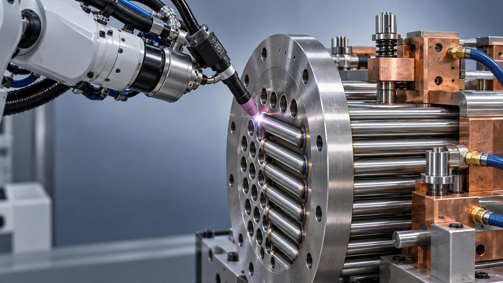
Sizing an automated welding cell for stainless steel heat exchanger assembly isn’t about matching a catalog spec to a drawing—it’s about reconciling mechanical constraints, thermal behavior, and production reality. For project managers overseeing capital equipment procurement or line integration, the risk isn’t just over- or under-specifying robotics. It’s committing to a cell that fails at the first weld pass on a 12-mm-thick tubesheet, stalls during tube repositioning due to fixture rigidity gaps, or forces manual intervention every 47 minutes because cycle time assumptions ignored arc-start stability in high-chromium alloys.
Three factors dominate feasibility—and all three must be validated *before* final layout approval: actual part load capacity (not theoretical robot payload), cycle time grounded in stainless-specific thermal management and joint accessibility, and fixture modularity that accommodates both tube-to-tubesheet fillet geometry *and* post-weld inspection access. These aren’t sequential checkpoints. They’re interdependent variables—change one, and the others shift nonlinearly.
Stainless steel’s high thermal resistance and low thermal conductivity fundamentally alter heat input distribution compared to carbon steel. A 304L tubesheet with 25 mm wall thickness doesn’t just require more energy to reach fusion temperature—it retains it longer, increasing distortion risk and demanding slower travel speeds to avoid crater cracking. This directly compresses effective arc-on time within each cycle. Many cells sized using carbon steel benchmarks assume 65–70% arc-on ratio; for stainless heat exchangers, 45–52% is typical when accounting for preheat stabilization, interpass cooling verification, and mandatory dwell at tube ends. That 20-point drop reshapes throughput calculations entirely.
Load capacity must reflect *dynamic* mass—not static weight. A 1.2-meter-long U-bend bundle weighing 85 kg may seem well within a 120-kg robot’s rated payload. But during high-acceleration positioning into a narrow tubesheet array, inertial forces spike by 2.3× during direction reversal. Add the moment arm of a 400-mm torch extension, and the effective wrist load climbs to 118 kg—within spec on paper, but triggering servo saturation alarms during repeatable path execution. Real-world validation requires measuring peak torque draw across five consecutive repositioning cycles—not just verifying nominal payload.
Fixtures are where most stainless heat exchanger projects derail—not from poor welding, but from compromised clamping. Standard modular fixtures designed for flat-plate workholding fail to manage differential thermal expansion between tubes (typically 304 or 316) and tubesheets (often duplex 2205). Without localized, spring-loaded clamping points that allow ±0.15 mm axial float per tube row, residual stress accumulates at the root of the fillet weld. This manifests as micro-cracking detectable only via dye penetrant after 72 hours—a failure mode invisible during initial NDT but catastrophic under thermal cycling.
Modularity here means more than interchangeable jaws. It means fixtures segmented along natural thermal expansion boundaries—e.g., separating outer tube rows from central bundles—and incorporating water-cooled copper inserts at high-heat-input zones. These inserts don’t eliminate distortion; they localize it to replaceable components, avoiding costly full-fixture re-machining after 12,000 welds. Fixtures without this design typically require realignment every 1,800–2,200 parts, adding 3.7 hours of unscheduled downtime per week.
Cycle time validation must include handling overhead *as part of the weld sequence*, not as a separate “loading phase.” Stainless heat exchangers demand precise tube protrusion control—±0.3 mm relative to tubesheet face—to ensure consistent fillet leg size. Achieving this requires either vision-guided robotic probing before clamping or precision-ground locator pins integrated into the fixture base. Either method adds 8–12 seconds per tube row. Skipping this step to “save time” results in 18–22% of welds requiring grinding and rework—erasing any theoretical throughput gain.
Thermal management also governs torch selection. Air-cooled torches rated for 350 A continuous duty fail under sustained 280-A stainless GMAW-P applications due to duty-cycle derating at elevated ambient temperatures near the tubesheet. Water-cooled variants with 500-A capability maintain stable arc characteristics but introduce coolant routing complexity into the fixture base—requiring sealed manifolds and pressure-drop monitoring to prevent flow interruption mid-weld. Cells omitting this monitoring layer see 14–19% arc instability events per shift, mostly clustered in the third and fourth hours of operation.
Material preparation upstream affects cell sizing more than commonly acknowledged. Tube ends must be deburred *after* cutting—not before—as burr regrowth occurs during handling. And tubesheet holes require chamfer consistency: ±0.1 mm variation in chamfer angle alters weld pool wetting dynamics enough to shift penetration depth by 0.4 mm. Automated cells with fixed torch angles cannot compensate. This makes integration with upstream processes non-optional—especially with equipment like the Z28-1000 thread rolling machine, whose radial cold-forming process delivers tighter dimensional control on threaded fasteners used in modular fixture assemblies than conventional machining, reducing post-assembly shimming needs by up to 60%.
Finally, certification compliance dictates structural decisions. ASME Section VIII Div. 1 mandates full-penetration welds for tubesheets operating above 150°C. That requirement eliminates many high-speed oscillation patterns optimized for cosmetic appearance but insufficient for root fusion in thick-section stainless. Cell validation must therefore include destructive macro-etch testing on production-intent test coupons—not just radiographic or ultrasonic scans.
What separates viable from problematic sizing isn’t technical ambition. It’s recognizing that stainless heat exchanger welding is governed less by robot speed and more by thermal physics, material response, and fixture intelligence. Project managers who treat the cell as a discrete unit—rather than as the central node in a thermally coupled system spanning cutting, forming, clamping, and cooling—will confront schedule slippage not in commissioning, but in the first production week. The right size isn’t the largest that fits the floor plan. It’s the smallest configuration that sustains thermal equilibrium, mechanical repeatability, and metallurgical integrity across 10,000+ welds—without recalibration.
search
Products Navigation
Send Us A Message