




How welding robot for H beam handles mismatched web-to-flange fit-up tolerances above 1.2mm
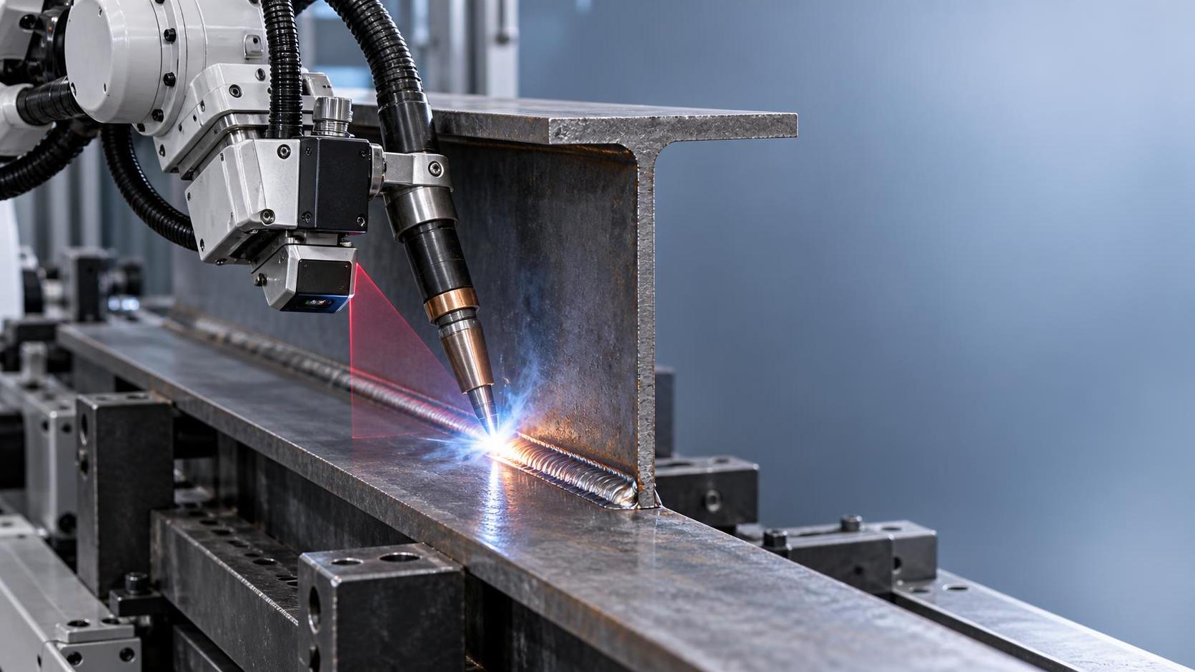
When Web-to-Flange Fit-Up Exceeds 1.2mm: What an H-Beam Welding Robot Can—and Cannot—Compensate For
If you’re running an H-beam production line and routinely encounter web-to-flange fit-up gaps over 1.2 mm, you’re not facing a rare edge case—you’re confronting a daily operational reality for many structural fabricators working with mill-delivered steel or second-hand material. The question isn’t whether your welding robot *can* weld under those conditions. It’s whether it can do so without sacrificing penetration control, bead uniformity, or long-term joint integrity—and without turning every beam into a rework candidate.
The short answer: yes—but only if the system is engineered for adaptive seam tracking, not just programmed for ideal geometry. A standard welding robot for H beam configured for nominal ±0.5 mm tolerances will either abort at the first mismatch, force-feed the torch into misalignment (risking lack of fusion), or rely on operator intervention mid-cycle. That’s where real-world capability diverges from spec-sheet promises.
Three Real Limits You Must Test—Not Assume
1. Arc tracking resolution matters more than robot repeatability. A robot with ±0.08 mm path repeatability means little if its seam-tracking sensor samples at 20 Hz with ±0.3 mm lateral resolution. At 1.2–2.0 mm fit-up variance, the torch must detect and react to vertical step changes *between* flange and web—not just follow a pre-taught path. Systems using laser triangulation with sub-millimeter Z-axis sampling (e.g., 0.05 mm vertical resolution at 100 Hz) handle this consistently. Older CCD-based or through-arc sensing systems often lag or overshoot, leading to inconsistent root penetration on the web side and excessive convexity on the flange side.
2. Oscillation isn’t optional—it’s functional compensation. Fixed-width oscillation (e.g., 4 mm preset) fails when fit-up varies across a single weld pass. Intelligent oscillation—where amplitude and dwell time adjust in real time based on gap width and joint geometry—is non-negotiable above 1.2 mm. In practice, this means the system must correlate sensor input with torch position *and* current/voltage feedback to modulate wire feed speed within milliseconds. Without that closed-loop response, you’ll see undercut on tight-fit zones and porosity or spatter on open gaps—even with perfect parameter setup.
3. Fixturing tolerance stacks against you—not with you. Many operators assume “the robot fixes everything.” It doesn’t. If your beam alignment fixture allows 0.8 mm lateral drift *plus* 0.6 mm web bow *plus* 0.7 mm flange twist, you’re already at 2.1 mm effective misalignment before the torch even starts moving. No sensor compensates for gross mechanical instability. Verify fixture rigidity under load—not just static tolerance—and measure actual beam deformation *after clamping*, not just before. A robot for H beam works best when it corrects micro-variance—not macro-instability.
Where Manual Intervention Still Wins (and When to Accept It)
There’s a persistent myth that high-end automation eliminates all manual prep. Truth is: above ~1.8 mm consistent fit-up error, grinding or localized pre-weld tacking often delivers better ROI than pushing robotic compensation to its limits. Why? Because each millimeter beyond 1.2 mm increases arc instability exponentially—not linearly. At 2.2 mm, even adaptive systems show >15% increase in rework rate due to intermittent short-circuiting or arc blow, especially on low-alloy steels common in construction-grade H-beams.
This isn’t failure—it’s physics. And recognizing that boundary helps prioritize effort: invest in upstream straightening and flange alignment (e.g., hydraulic leveling stations or CNC edge milling) *before* relying on robotic compensation as a crutch. One client in Vietnam reduced average fit-up variance from 1.9 mm to 0.7 mm by adding a dedicated pre-weld flange squaring station—cutting robotic rework by 65% and increasing usable duty cycle per robot cell.
Material and Joint Design Constraints You Can’t Out-Program
Fit-up tolerance isn’t isolated—it interacts directly with material properties and joint design:
- Carbon vs. alloy steels: Higher carbon equivalents (>0.45%) reduce allowable gap tolerance before cold cracking risk rises—even with preheat. A robot won’t change metallurgy.
- Flange thickness asymmetry: If one flange is 25 mm and the other is 16 mm, thermal distortion during welding pulls the web toward the thicker side. Compensating for initial fit-up doesn’t prevent post-weld camber—only proper sequencing (e.g., welding flanges alternately) does.
- Weld sequence dependency: Single-pass fillet welds tolerate larger gaps than multi-pass groove welds. But if your specification requires full-penetration welds on thick webs, 1.2 mm mismatch may already exceed ASME Section IX PQR validity limits—regardless of robot capability.
None of these are robot shortcomings. They’re constraints built into code compliance, material behavior, and thermal physics. Ignoring them turns a capable welding robot for H beam into a costly compliance liability.
A Practical Decision Framework for Your Next Cycle
Before committing to new equipment—or adjusting parameters on existing units—ask these three questions:
- What’s your *measured* 90th-percentile fit-up variance across 100 recent beams—not the theoretical max? If it’s consistently ≤1.0 mm, focus on process stability (gas flow, contact tip wear, wire stick-out). If it’s ≥1.6 mm, robotics alone won’t solve it; reassess material sourcing or pre-assembly workflow.
- Are your welders using the robot’s full adaptive toolkit—or just running pre-programmed paths? Many shops never enable real-time oscillation modulation or auto-adjusting voltage windows because training lags behind hardware. Capability ≠ utilization.
- Does your inspection protocol catch mismatch-related defects *before* final NDT? Visual checks at 500 mm distance miss undercut in deep gaps. If your QA still relies on post-weld PT/UT without in-process monitoring, you’re validating failure—not preventing it.
One last note: while welding robots handle fit-up challenges, downstream processes like thread rolling depend on dimensional consistency *after* welding. For example, anchor bolts or T-shaped screws used in H-beam connections require precise external threads—often rolled cold on equipment like the Z28-500 thread rolling machine. Its radial cold-forming process improves fatigue strength and surface finish—but only if the base material’s hardness stays below HRC37 and elongation exceeds 10%. That’s another reason why controlling weld-induced distortion early matters: it protects the integrity of subsequent high-precision operations.
Bottom line: A welding robot for H beam isn’t a tolerance eraser. It’s a precision tool that extends your process window—within physical and metallurgical boundaries. Respect those boundaries, verify them with actual data—not assumptions—and you’ll get consistent welds, not just consistent motion.
search
Products Navigation
Send Us A Message