




Laser Cutting Loading Robot Failures: Top 3 Causes of Misloading (Material Warping, Edge Detection Lag, Clamp Force Drift) and Fixes
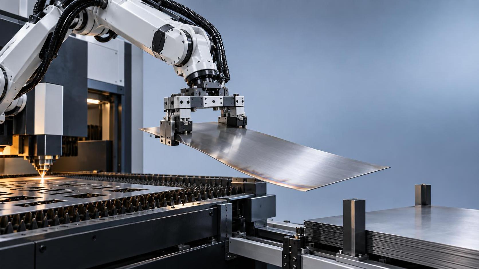
Laser cutting loading robot failures—especially misloading—directly disrupt material flow, risk sheet deformation, and introduce positioning errors that propagate into cut quality. When a blank fails to seat correctly on the shuttle table or pallet, subsequent motion commands assume incorrect reference geometry. The result is either aborted cycles, collision alerts, or—more insidiously—successful but misaligned cuts that pass initial inspection only to fail downstream assembly. Three interrelated physical phenomena dominate field-observed misloading events: thermal-induced material warping, edge detection lag from sensor drift, and clamp force drift in pneumatic or hydraulic actuation systems. Each has distinct root causes, observable failure signatures, and requires condition-specific intervention—not generic recalibration.
1. Material Warping: Not Just Flatness Tolerance—It’s Dynamic Thermal Memory
Warping isn’t merely an incoming material defect—it’s a time-dependent response to residual stress release triggered by ambient temperature shifts and localized heating during prior processing. A 3mm stainless steel sheet stored overnight at 18°C may exhibit ≤0.3mm deviation across its surface. But after uncoiling from a tensioned coil or exposure to direct sunlight on a loading dock, that same sheet can develop 1.2–2.5mm bowing along its length within 90 minutes. Standard flatness sensors (e.g., capacitive arrays or laser triangulation lines) detect only static profile at the moment of scanning. They do not account for how the sheet relaxes *during* transfer—particularly when gripper fingers engage near edges while center mass remains unsupported. This relaxation occurs mid-motion, causing lateral shift or angular tilt before clamping completes.
Fix: Implement real-time warp compensation using dual-point dynamic height monitoring. Mount two high-response inductive sensors—one at each end of the shuttle path—configured to trigger micro-adjustments to Z-axis lift height *during* engagement. Calibration must be performed with representative material grades and thicknesses (e.g., 1.5mm cold-rolled vs. 6mm hot-rolled carbon steel), not just nominal specs. For high-mix environments, store material-specific compensation profiles linked to alloy code and thickness in the robot’s PLC memory—not as global offsets. Also verify that shuttle table support rollers are aligned to ±0.05mm parallelism; misaligned rollers amplify warping effects during acceleration.
2. Edge Detection Lag: When “Seen” ≠ “Located”
Edge detection lag manifests as consistent X/Y offset in loaded position—typically 0.4–1.8mm—despite passing static calibration checks. This occurs because most vision-based or proximity-sensor systems rely on fixed trigger thresholds calibrated against clean, dry, oxide-free edges. In practice, mill scale, light oil film, or even condensation alters reflectivity or dielectric properties. A sensor calibrated on bare CRCA steel may read 0.7mm late on galvanized sheet due to zinc layer scattering. Worse, thermal expansion of the sensor housing itself—especially in non-climate-controlled facilities—shifts optical alignment over 8-hour shifts. Field data shows detection latency increases by ~0.12ms per °C rise above 22°C ambient, accumulating measurable positional drift after prolonged operation.
Fix: Replace static threshold logic with adaptive edge-sensing recalibration. Configure the system to run a brief (≤3-second) validation scan every 12 loading cycles using a known reference edge—a machined steel gauge block mounted beside the load station. The controller compares measured edge position against stored nominal coordinates and adjusts gain and offset parameters automatically. Crucially, this recalibration must occur *after* the gripper has released the sheet but *before* clamping initiates—ensuring no mechanical interference skews the reading. Avoid recalibrating during active cutting; vibration and thermal noise degrade accuracy. Also inspect lens cleanliness weekly—smudges cause asymmetric blur that mimics edge lag.
3. Clamp Force Drift: The Hidden Hydraulic Creep
Clamp force drift rarely triggers alarms—it silently degrades repeatability. Pneumatic clamps lose 8–15% holding force over 6 months due to seal compression set and moisture-induced corrosion in cylinder bores. Hydraulic systems suffer from gradual fluid degradation and micro-leakage at manifold joints. A nominal 1200N clamp force may drop to 980N without fault indication, allowing sheet slippage under shuttle acceleration (typically 0.8–1.2g). This slippage is often masked by the robot’s position feedback loop, which reports correct endpoint coordinates while actual sheet position lags behind.
Fix: Install closed-loop clamp pressure monitoring with analog feedback. Use inline pressure transducers (not switch-based) wired directly to the motion controller’s analog input channel. Set dynamic tolerance bands—not fixed thresholds—based on material thickness and yield strength. For example, 1.0mm aluminum requires ≥650N; 8mm mild steel needs ≥2100N. The controller must compare real-time pressure against the required minimum *during clamping*, not just at initiation. If force falls below tolerance for >150ms, abort loading and log a “clamp integrity warning”—not a generic “misload.” Also replace pneumatic filter-regulators every 4,000 operating hours; clogged filters cause inconsistent air delivery even with stable supply pressure.
These three causes rarely occur in isolation. A warped sheet increases edge detection uncertainty, which in turn prompts the system to apply excessive clamp force—accelerating seal wear and initiating drift. That’s why diagnostics must examine the chain: review PLC logs for sequence timing (e.g., time between edge detection confirmation and clamp activation), cross-check environmental logs (temperature/humidity at load station), and physically measure sheet profile *immediately after unloading*—not just upon receipt. For long workpiece handling applications requiring synchronized motion control—such as those supported by the 7 axis cantilever type welding robot—consistent loading geometry directly affects seam tracking stability and weld bead uniformity. Misloaded blanks introduce cumulative coordinate errors that compound across multi-pass operations, especially on parts exceeding 6 meters where thermal distortion accumulates over extended travel paths. Precision begins before the first cut—and ends only when every subsystem operates within its verified, material-aware envelope.
search
Products Navigation
Send Us A Message