




Press Brake Loading Robot Integration Checklist: Tool Changer Compatibility, Safe Stop Timing, and Sheet Alignment Verification Steps
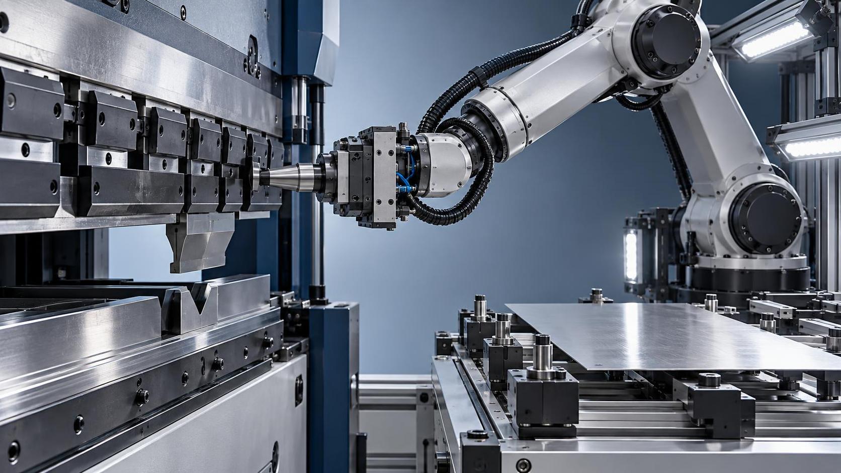
Press Brake Loading Robot Integration: Three Validation Steps You Can’t Skip
Integrating a press brake loading robot isn’t just about bolting hardware together and flipping a switch. In real-world metal fabrication shops—especially those running mixed batches, tight tolerances, or multi-shift operations—the difference between smooth automation and recurring downtime often comes down to three precise validation steps: tool changer compatibility, safe stop timing, and sheet alignment verification. These aren’t theoretical checkboxes. They’re field-tested thresholds that determine whether your robot delivers consistent part quality—or becomes a source of scrap, rework, and operator hesitation.
At Wuxi Samgins International Trade Co., Ltd., we’ve supported press brake automation deployments across Southeast Asia, Europe, and the Americas since 2012—not as system integrators selling turnkey black boxes, but as equipment specialists who’ve seen how mismatched tooling interfaces stall production, how delayed safety stops trigger unplanned lockouts, and how sub-millimeter misalignment cascades into costly bend errors. Our ISO 9001-certified and CE-compliant bending machines, shearing systems, and robotic handling solutions are designed with these integration realities in mind. That includes supporting customers who also rely on complementary high-precision processes—like cold-forming threads on anchor bolts or T-shaped screws using radial feed methods. For example, when fabricating structural components for construction, some teams pair press brake automation with a Z28-500 thread rolling machine to produce high-strength fasteners without chips or heat distortion—making alignment consistency across both processes even more critical.
1. Tool Changer Compatibility: It’s Not Just About Physical Fit
A robot arm may reach the tool rack, but if its gripper doesn’t match the clamping geometry, stroke depth, or release signal protocol of your press brake’s quick-change system, you’ll get false positives—tools that appear seated but aren’t fully locked—or worse, partial engagement that damages tool holders over time.
Start by verifying three layers:
- Mechanical interface: Does the robot’s end-effector match the tool holder’s mounting standard (e.g., ISO 2662, DIN 69871)? Pay attention to taper angle tolerance—±0.5° deviation can cause slippage under load.
- Signal handshake: Most modern press brakes use digital I/O or fieldbus (PROFINET, EtherCAT) to confirm tool presence and position. Your robot controller must support the same handshake logic—not just “tool inserted,” but “tool verified at full torque.”
- Tool library mapping: If your press brake uses tool ID tags (RFID or optical), ensure the robot’s vision or sensor system reads them *before* placement—and cross-checks against the CNC program’s requested tool ID. Skipping this step leads to wrong-tool bends, especially during unattended night shifts.
We’ve seen cases where identical-looking tool changers from different OEMs behave differently under thermal expansion. A 3°C ambient shift in a non-climate-controlled shop can widen clearance enough to break electrical continuity in low-voltage sensing circuits. That’s why our field support always includes thermal soak testing—not just cold-start validation.
2. Safe Stop Timing: ISO 13857 Isn’t Optional—It’s Measurable
Safe stop timing isn’t about hitting a generic “fast enough” number. It’s about calculating the total stop time—including robot deceleration, press brake hydraulic response, and physical ram movement—and confirming it stays within the separation distance defined by ISO 13857 (for body parts) and ANSI B11.19 (for safeguarding performance). If your robot places a sheet and then stops—but the ram hasn’t fully halted before the next cycle starts—you risk pinch-point incidents, even with light curtains active.
Here’s how to validate it:
- Use a calibrated motion capture system or high-speed camera (≥1,000 fps) to record ram position vs. robot motion during emergency stop initiation—not just power-off tests, but actual E-stop sequences triggered mid-cycle.
- Measure stop time from the *first* safety input activation (e.g., light curtain breach) to full ram rest—not from PLC command to motor disable. Hydraulic accumulators and servo valve lag matter.
- Verify that the calculated safe distance (using formula S = (K × T) + C from ISO 13857) accounts for both robot reach envelope *and* ram travel path—not just static positions.
This isn’t a one-time setup. We recommend quarterly re-validation—especially after firmware updates or hydraulic fluid changes. One customer in Germany discovered their stop time increased by 120 ms after switching to a higher-viscosity oil. That pushed them outside the safe zone for hand-access zones near the back gauge.
3. Sheet Alignment Verification: Precision Starts Before the First Bend
Robots don’t “see” like humans. They interpret vision data through calibration, lighting, and contrast thresholds. A sheet may look aligned on screen—but if the edge detection algorithm misreads mill scale, oil film, or minor curl, the resulting offset compounds across successive bends.
Don’t rely solely on camera-based edge detection. Combine it with:
- Tactile reference points: Use pneumatic or servo-driven locators that physically contact the sheet’s corner or flange *after* initial placement—then feed that positional correction back into the robot’s coordinate frame.
- Multi-angle lighting: Diffuse backlighting alone misses subtle warpage. Add angled LED strips to highlight edge roll or bow—especially critical for stainless or aluminum sheets above 2 mm thickness.
- Real-time feedback loop: Compare first-bend results (measured via laser scanner or probe) against CAD model tolerances. If alignment drift exceeds ±0.3 mm over five consecutive parts, trigger an automatic recalibration sequence—not just an alarm.
This matters most when feeding material into secondary processes. For instance, if those bent panels later go into a thread rolling line—like the Z28-500 thread rolling machine used for anchor bolts in construction applications—the dimensional stability of the base plate directly affects thread concentricity and load-bearing integrity.
What Comes Next?
None of these steps replace thorough risk assessment or documented validation protocols. But they do reflect what operators actually encounter when scaling up from manual bending to semi-automated workflows: not abstract compliance, but tangible, repeatable checks rooted in physics, timing, and material behavior. If you’re evaluating a press brake loading robot—or troubleshooting one already installed—start here. Confirm tool changer handshake logic under thermal load. Time your safe stop with instrumentation, not assumptions. Validate alignment using tactile + optical redundancy, not just software confidence.
Wuxi Samgins supports this work with technical documentation aligned to ISO 9001 and CE requirements—and with application engineers who’ve configured bending lines from Shanghai to São Paulo. What matters most isn’t how many robots you install, but how reliably each cycle meets specification—without requiring constant operator intervention.
search
Products Navigation
Send Us A Message