




Solving Large-Workpiece Access Problems with a Movable 7-Axis Welding Robot
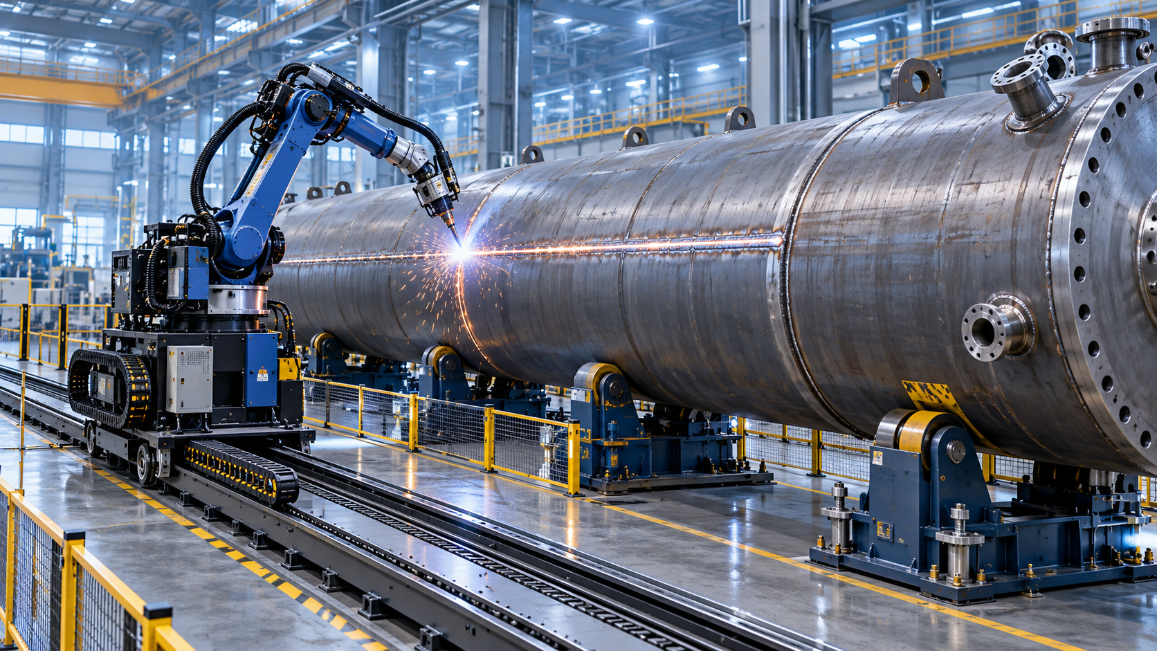
Solving Large-Workpiece Access Problems with a Movable 7-Axis Welding Robot
Welding large workpieces often creates access challenges, especially when fixed robots cannot reach complex joints or changing weld positions.
A movable 7 axis welding robot gives operators the flexibility to work around oversized structures with greater precision, consistency, and safety.
This article explains how mobile robotic welding solutions improve access, reduce setup limitations, and support efficient production in demanding fabrication environments.
Why Large Workpieces Create Serious Welding Access Problems
Large tanks, pressure vessels, frames, ship sections, construction machinery, and heavy structures rarely present simple welding conditions for operators or automated equipment.
The workpiece may be too long, too high, too heavy, or too difficult to rotate safely on conventional positioners.
In many workshops, operators must weld overhead joints, confined corners, deep seams, curved surfaces, and areas behind stiffeners or structural reinforcements.
These conditions can make manual welding slower, physically demanding, and less consistent, particularly when long seams require stable travel speed and torch angle.
A fixed industrial robot can automate repetitive welding, but its working envelope remains limited by installation position, rail length, and fixture layout.
When the component exceeds the robot cell boundary, fabricators may need to move the workpiece repeatedly or build expensive dedicated handling systems.
Moving a large workpiece is often more difficult than moving the welding robot, especially when lifting equipment availability is limited.
Each repositioning step also introduces delays, alignment checks, safety risks, and opportunities for dimensional deviation between connected weld sections.
For operators, the practical problem is simple: the welding torch must reach the seam at the correct angle without forcing unsafe body positions.
For production teams, the larger problem is maintaining weld quality while reducing handling time, idle time, and dependence on highly specialized manual skills.
What Makes a Movable 7 Axis Welding Robot Different
A movable 7 axis welding robot combines robotic welding repeatability with additional freedom to approach difficult seams around large or fixed structures.
The first six axes typically control the robot arm, allowing the torch to travel, rotate, and maintain orientation along programmed weld paths.
The seventh axis usually provides external movement, such as travel on a rail, mobile base, gantry system, or extended linear track.
This added motion expands the available working range without requiring the entire workpiece to be repositioned after every accessible weld section.
Instead of treating the robot as a stationary cell machine, operators can use it as a flexible welding resource for larger fabrication zones.
The movable configuration is especially useful when seams extend across long distances or appear at several locations around the same assembly.
It can also support workpieces that remain fixed on floor supports, roller beds, assembly fixtures, rotators, or structural fabrication tables.
However, extra reach alone does not guarantee better results. The robot, track, fixtures, welding process, and programming strategy must work together.
The best application is one where movement reduces unnecessary handling while preserving stable torch-to-joint distance, wire feed conditions, and shielding gas coverage.
Which Access Challenges Can the Robot Solve Effectively
A movable 7 axis welding robot is particularly effective for long longitudinal seams on tanks, beams, large plates, vessel shells, and fabricated enclosures.
It can travel alongside the component while the arm makes smaller orientation corrections to keep the welding torch aligned with the joint.
This is useful when weld length exceeds the normal arm reach of a fixed robot or when several seams are distributed along one structure.
Corner joints and intersecting members also benefit from the extra axis because the robot can approach each area from a more favorable position.
Operators can avoid excessive robot arm extension, which may reduce stiffness, limit path accuracy, or create difficult cable and hose routing conditions.
For curved shells and cylindrical assemblies, the external axis can coordinate with rotators or positioners to maintain a more consistent welding posture.
In heavy fabrication, the workpiece may not be practical to rotate at all. A robot that moves around it becomes a more realistic automation option.
Large structural components with multiple weld zones can also be programmed as a sequence, reducing the time spent relocating equipment between operations.
Still, inaccessible areas behind permanent obstructions may require fixture changes, alternative torch configurations, or manual welding for final completion.
Robotic welding should therefore be evaluated seam by seam rather than assumed to replace every manual weld on a complex product.
How Operators Benefit from Better Reach and Stable Welding Positions
For daily operators, the most immediate advantage is reduced exposure to uncomfortable welding positions, heat, fumes, spatter, and repetitive physical strain.
Instead of manually following a long seam across a large assembly, the operator can supervise travel, verify parameters, and manage quality checkpoints.
This changes the role from continuous torch handling toward process control, fixture preparation, program selection, and response to production variation.
Stable robotic travel helps maintain consistent travel speed, stick-out, torch angle, weaving pattern, and overlap between adjacent weld passes.
Those variables strongly influence bead appearance, penetration, fusion quality, spatter levels, and the amount of downstream grinding or repair work.
Repeatability is especially valuable when the same product family is produced regularly, even if dimensions vary within a defined range.
Operators can store validated welding programs and reuse them after confirming workpiece position, joint condition, material grade, and required weld procedure.
That does not eliminate the need for skilled personnel. Operators must still inspect fit-up, identify gaps, monitor consumables, and verify actual welding behavior.
A capable operator recognizes when a programmed path no longer matches production reality, such as plate distortion, tack weld interference, or incorrect assembly dimensions.
Successful robotic welding cells depend on this practical judgment as much as they depend on the robot's motion capability.
Prepare the Joint Before Automated Welding Begins
Robotic welding performance begins before the arc starts. Poor edge preparation, inconsistent root gaps, and distorted plates can defeat an otherwise capable robot system.
Large-workpiece fabrication often requires long bevels with controlled angles, uniform root faces, and clean surfaces that support repeatable joint fit-up.
When bevel geometry changes along the plate edge, the welding robot may require path corrections, different parameters, or additional passes to achieve sound results.
Consistent bevel preparation reduces these variables and helps operators create more reliable welding programs for thick plates and heavy assemblies.
For tank, vessel, and structural applications, Beveling & Milling Edge For Heavy Tank can support accurate edge preparation before robotic welding.
The equipment can form straight, inclined, U-shaped, V-shaped, and K-shaped bevels in one pass, reducing secondary grinding requirements.
Its adjustable bevel range can typically reach 0 degrees to 90 degrees, while certain configurations support specialized angle ranges for defined joint designs.
Standard machines process plate thicknesses from 6 mm to 80 mm, while heavy-duty non-pressure beam designs can handle 6 mm to 400 mm.
For operators, stable edge preparation means less time compensating for irregular joint geometry during robot teaching and production welding.
It also helps reduce variation between workpieces, which is essential when programming long seams on large structures with limited tolerance for rework.
How to Set Up a Movable Robot for Large Assemblies
Before programming begins, operators should inspect the full work area, including seam locations, robot travel path, cable routes, fixtures, and safety boundaries.
The robot track or mobile base must have adequate travel distance to cover all intended welding zones without approaching mechanical end limits.
Workpiece supports should hold the assembly securely while allowing access to the seam and preventing vibration during welding travel.
For long plates or shell sections, sagging and thermal distortion must be considered because they can change joint position during the weld sequence.
Reliable fixturing does not always mean highly complex tooling. It means repeatable locating points, stable clamping, and sufficient clearance for the torch.
Operators should verify that the robot can approach the beginning, middle, and end of every seam without singularities, collisions, or excessive wrist rotation.
Dry runs without arc welding are important for checking reach, cable movement, torch clearance, and potential interference from clamps or temporary supports.
Where components vary, seam tracking or touch sensing can help locate the joint, but these systems should not replace basic fit-up discipline.
Clear reference points make recovery easier after production interruptions, maintenance work, power loss, or a required operator adjustment.
A documented setup routine also helps different shifts achieve consistent results instead of relying on one experienced operator's memory.
Choosing Welding Parameters for Long and Difficult Seams
Correct robot motion does not automatically produce acceptable welds. Welding current, voltage, wire feed, travel speed, shielding gas, and torch angle remain critical.
Operators should begin with qualified welding procedures and then confirm that the programmed robot path supports those parameters under real production conditions.
Long seams can create heat accumulation, especially on thick plates, closed structures, and assemblies with limited heat dissipation capacity.
Heat buildup may increase distortion, change joint fit-up, or affect the consistency of later weld passes along the same workpiece.
Program sequencing can reduce this risk by alternating weld locations, using balanced welding patterns, or allowing controlled cooling between critical passes.
For multi-pass bevel joints, the robot must maintain correct layer placement and avoid excessive undercut, lack of fusion, or incomplete interpass cleaning.
Operators should verify wire, contact tips, liners, gas nozzles, and grounding points before production, because long robotic cycles magnify consumable problems.
A simple inspection after the first completed part is more valuable than discovering a parameter issue after several large assemblies have been welded.
Where code compliance is required, visual inspection, dimensional checks, non-destructive testing, and production records should follow the applicable welding standard.
Safety Controls Matter More When the Robot Moves
A movable robot creates a larger operating zone than a conventional fixed cell, so safety planning must cover the complete travel envelope.
Operators need clearly defined protected areas, emergency stops, access controls, warning devices, and procedures for teaching, maintenance, and fault recovery.
Traveling equipment can create pinch points near rails, supports, cables, fixtures, and surrounding machinery, particularly in crowded heavy fabrication workshops.
Personnel should never enter the robot operating area during automatic welding unless the system is in an approved safe mode.
Proper cable management is also essential. Welding cables, gas lines, and control connections must move smoothly without snagging or excessive bending.
Before each shift, operators should inspect track condition, mounting bolts, travel limits, protective barriers, torch components, and emergency stop function.
When workpiece geometry changes, the safety review should change with it. New fixtures or taller components can introduce new collision hazards.
Training should cover both normal operation and abnormal situations, including arc faults, wire feeding issues, collision alarms, and unexpected path obstruction.
When a Movable 7 Axis Welding Robot Is a Good Investment
A movable robotic solution is most suitable when workpieces are large, weld volume is meaningful, and handling the component is more difficult than moving the robot.
It is especially compelling for repeat or semi-repeat production involving tanks, pressure vessels, beams, frames, large plate assemblies, and heavy equipment structures.
The business case improves when manual welding causes bottlenecks, quality variation, ergonomic concerns, lengthy repositioning, or frequent dependence on scarce skilled welders.
Fabricators should compare total workflow time rather than only arc time. Material handling, fit-up, programming, inspection, rework, and fixture changes all affect return.
A low-volume workshop may still benefit if the robot can serve multiple product families and move between several defined welding stations.
Conversely, highly variable one-off work with poor fit-up may require process improvement before automation can deliver predictable value.
The strongest candidates have stable joint designs, sufficient production repetition, reliable upstream preparation, and an operator team willing to manage robotic processes.
Equipment selection should consider payload, reach, track length, welding power source compatibility, sensing options, service support, and future product changes.
For heavy fabrication lines, coordinated edge preparation and mobile robotic welding can create a more controlled path from plate processing to final assembly.
Conclusion
A movable 7 axis welding robot solves large-workpiece access problems by bringing controlled robotic motion closer to the weld instead of repeatedly moving the assembly.
Its value comes from better reach, more consistent torch positioning, reduced operator strain, and fewer handling interruptions across long or complex welding operations.
For operators, successful use depends on accurate joint preparation, stable fixturing, practical programming, routine inspections, and active monitoring of actual weld conditions.
When these fundamentals are in place, mobile robotic welding can make oversized fabrication work more predictable, safer, and easier to scale without sacrificing weld quality.
search
Products Navigation
Send Us A Message