




What H-Beam Size Variation Can a Welding Robot Handle?
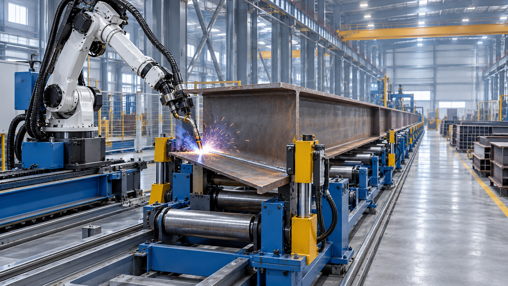
What H-Beam Size Variation Can a Welding Robot Handle?
H-beam fabrication rarely involves one perfectly repeated section. A steel structure workshop may process relatively light members for platforms and frames in the morning, then switch to deeper, heavier beams for industrial buildings, bridges, machinery bases, or warehouse structures later in the day. Flange width, web height, beam length, plate thickness, joint preparation, and allowable distortion can all change from order to order.
That is why the practical question is not simply whether a welding robot can weld an H-beam. It is: what range of H-beam sizes can the complete robotic welding cell process repeatedly, safely, and within the required weld-quality standard? The answer depends on more than the robot arm. A robot, positioner, conveying system, clamping arrangement, welding power source, seam-tracking method, and control program must work as one system.
Can a welding robot improve consistency in steel structure welding? In many suitable applications, yes. However, consistency does not come from automation alone. It comes from controlling the beam position, joint fit-up, welding path, heat input, and handling sequence across the full dimensional range that the line is expected to cover.
The H-Beam Size Range Is a System Capability
When buyers ask for a robotic H-beam welding solution, “size range” is often treated as a single figure. In practice, it should be separated into several dimensions. A cell may have enough reach to access a tall web but lack a fixture that can hold a narrow flange securely. It may accept a long beam on its conveyor but have difficulty rotating a heavy assembly. It may weld the required fillet joint, yet lose repeatability when incoming plate fit-up changes.
The main variables normally include:
- Web height: This affects torch access, robot reach, gantry clearance, and the distance between the two fillet welds.
- Flange width: Wider flanges require broader support and clamping coverage; very narrow flanges can create positioning challenges of a different kind.
- Beam length: Length determines the required travel distance for conveyors, roller beds, gantry tracks, and handling equipment.
- Plate thickness and weld size: These influence welding current, wire selection, travel speed, number of passes, preheating requirements, and distortion control.
- Assembly weight: Weight matters especially where turning rolls, rotators, lifting systems, or positioners are used.
- Straightness and fit-up condition: A robot can compensate for some variation when sensing is available, but it cannot turn severely inconsistent assembly into stable production without addressing the upstream process.
For this reason, a supplier should define the working envelope around the customer’s actual production mix rather than around the largest theoretical beam. The most useful specification is usually not “maximum beam size” alone, but a verified operating range stating minimum and maximum web height, flange width, length, thickness, weight, and joint type.
Robot Reach Is Only One Part of the Answer
A six-axis welding robot has a defined reach and payload, but the working envelope of an H-beam line can be much larger than the arm itself. In many steel structure applications, the robot is mounted on a linear rail, suspended from a gantry, or combined with a moving workpiece system. This allows the torch to travel along the beam while retaining controlled orientation at the weld joint.
For long beams, a fixed robot cell may be impractical unless the beam is indexed through the station. A rail-mounted robot or gantry system can be a better fit because the motion system follows the length of the workpiece. For deeper beams, the vertical stroke and lateral access geometry become equally important. The torch must maintain the correct work angle and travel angle on both sides of the web-to-flange joint, including near beam ends where access can be restricted.
There is also a distinction between reaching the joint and welding it well. A robot may physically access a seam at the edge of its workspace, but a near-maximum reach position can reduce flexibility for torch adjustment, anti-collision movement, cable management, or seam-search routines. A robust design leaves usable motion margin rather than treating the edge of the robot envelope as the normal production position.
Fixture Design Usually Determines Real Flexibility
The fixture is often the difference between a promising robotic demonstration and dependable shop-floor output. Before welding begins, the web and flanges must be aligned with sufficient accuracy for the specified joint. If the gap, offset, or angular mismatch changes excessively from beam to beam, the robot program cannot produce uniform weld geometry simply by repeating the same path.
An adjustable H-beam assembly and welding station may use movable side supports, hydraulic or mechanical clamping, guide rollers, datum references, and independently adjustable supports for different flange widths and web heights. The adjustment mechanism should be easy to set, clearly referenced, and stable under heat. If every size change requires lengthy manual measuring, the line may be technically flexible but commercially inefficient.
A useful design review asks several practical questions:
- How will the beam be centered when flange widths change?
- Can clamps accommodate thickness changes without marking or deforming the plate?
- Are supports close enough together to prevent sagging on longer workpieces?
- Can the station hold a tapered, cambered, or slightly distorted beam if such work is part of the order mix?
- What reference is used after a beam is rotated or transferred to the second welding side?
These details are not secondary mechanical issues. They directly affect seam location, torch-to-work distance, weld penetration, and repeatability.
Managing Variation in the Joint, Not Just the Beam
Two H-beams with identical nominal dimensions can still behave differently during welding. Plate cutting tolerances, edge condition, tack-weld quality, thermal distortion, and residual stress all influence the actual joint seen by the torch. This is particularly relevant in built-up beams, where the web and flange plates are assembled from separate components.
For stable robotic welding, upstream cutting and assembly should be considered part of the automation strategy. CNC cutting machines, edge milling equipment, and properly controlled fit-up stations can help create more predictable joint conditions before the beam reaches the robotic station. The aim is not to demand unrealistic perfection from fabrication staff; it is to prevent avoidable variation from being handed to an automated process that is designed for controlled repetition.
Seam-finding and seam-tracking technologies can provide additional tolerance for normal production variation. Depending on the welding process and application, the system may use touch sensing, arc sensing, laser-based detection, or programmed reference points. These functions can help the robot locate the joint and maintain its path, but they should be selected based on the actual surface condition, weld preparation, and production environment. Heavy scale, spatter, inconsistent tack welds, or unstable grounding can reduce the reliability of sensing methods.
Can a Welding Robot Improve Consistency in Steel Structure Welding?
A welding robot can improve consistency in steel structure welding when the workpiece is presented consistently and the welding procedure is properly developed. The robot follows the same programmed path, maintains planned travel speed, and applies repeatable motion at positions that can be tiring or difficult for manual welders to sustain over long production runs. This can be especially valuable on long continuous fillet welds in repetitive H-beam fabrication.
Consistency should not be confused with automatic acceptance of every weld. Welding parameters still need to be qualified for the material grade, thickness range, joint design, filler metal, shielding or flux arrangement, and required quality level. Inspection remains necessary. Depending on the contract and applicable fabrication requirements, this may involve visual inspection, dimensional checks, and other specified non-destructive examination methods. The robotic cell should support quality control rather than be treated as a substitute for it.
The greatest gain is often process discipline. Once the correct beam orientation, clamping method, torch angle, parameter set, and sequence are established, they can be repeated with less operator-to-operator variation. But if incoming dimensions change beyond the assumptions of the fixture or program, the same repeatability can reproduce the same defect. Automation makes an unstable process visible very quickly.
Size Changes Affect Throughput More Than Many Buyers Expect
A robotic line that handles a broad range of beam sizes is not necessarily the best choice for a high-volume, narrow-range product family. Wide flexibility commonly requires adjustable fixtures, more axes, more sensors, and additional setup steps. Those features are valuable for job shops and fabricators with varied contracts, but they can add complexity where production is highly standardized.
Conversely, a dedicated line optimized for a limited beam family may offer simpler setup and steadier material flow, yet become restrictive when new orders introduce a different flange width or web depth. The right balance depends on how often section sizes change, how much adjustment time is acceptable, whether the plant produces built-up or rolled sections, and whether the line must accommodate future projects.
Questions to Settle Before Selecting a Robotic H-Beam Line
The starting point should be a representative production list, not only a maximum drawing. Collect the smallest and largest beam sections expected, typical lengths, plate thicknesses, material grades, required weld sizes, joint types, annual or monthly production pattern, and quality requirements. It is also worth identifying the awkward parts: short members, cross-stiffeners, end plates, openings, intermittent welds, and beams with attachments. These are often where an apparently straightforward automated concept becomes more complicated.
Buyers should also clarify whether the system is intended for web-to-flange welding only or for a broader sequence that includes assembly, tack welding, straightening, end-face machining, drilling, or handling. The welding robot may be one station within an H-beam production line rather than an isolated investment. Material flow between stations affects labor requirements, safety, and the practical output of the entire operation.
Wuxi Samgins International Trade Co., Ltd., established in 2012 in Wuxi, Jiangsu Province, works with equipment categories that commonly intersect in this workflow, including welding robots, automatic welding equipment, CNC cutting machines, H-beam production line equipment, CNC machine tools, milling equipment, and end-face or edge milling machines. For fabricators evaluating a robotic solution, that broader equipment perspective is useful because beam quality is shaped before the welding torch starts moving. The company organizes production and design in line with its ISO9001 quality system and EU CE requirements for relevant equipment, while project-specific conformity requirements should always be confirmed for the destination market and final machine configuration.
A Practical Way to Define the Required Range
Rather than asking whether a welding robot can handle “large” H-beams, define an operating window. State the normal beam range that will account for most production, then list the occasional maximum and minimum sections separately. This prevents an entire line from being oversized for rare workpieces, while ensuring that exceptional beams are not overlooked during layout and fixture planning.
The final specification should confirm accessible weld positions, not merely workpiece dimensions. It should describe how the beam is loaded, aligned, clamped, transported, welded on each side, inspected, and removed. It should also identify changeover tasks and the expected condition of incoming assemblies. If a proposed system cannot explain these steps clearly, its stated size range may be more theoretical than practical.
A well-matched robotic cell can accommodate meaningful H-beam variation and deliver a more controlled welding process. The dependable range, however, is defined by the whole production system: robot geometry, motion axes, fixture adjustment, handling capacity, joint sensing, and upstream fabrication quality. Confirming those points early is the most reliable way to turn robotic welding from a standalone machine purchase into a workable steel structure production method.
search
Products Navigation
Send Us A Message