




What common joint defects occur when using an automatic space frame welding machine with mismatched tube wall thicknesses?
Why Mismatched Tube Wall Thicknesses Trigger Critical Joint Failures in Space Frame Welding
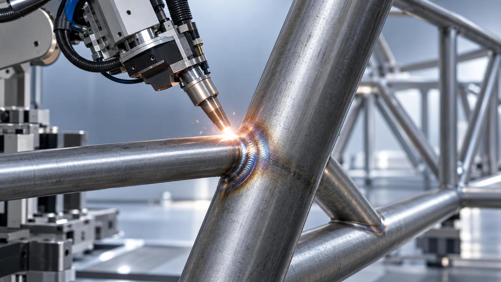
When an automatic space frame welding machine processes tubular members with inconsistent wall thicknesses—say, 4 mm meeting 6 mm or 8 mm abutting 3 mm—the resulting weld joints rarely fail catastrophically on first inspection. Instead, they degrade silently: micro-cracks hide beneath smooth surfaces, fusion zones shrink below specification, and residual stresses accumulate in ways that escape visual or even basic NDT screening. For quality control and safety managers responsible for structural integrity—especially in architectural supports, stadium roofs, or industrial mezzanines—this isn’t a “welding parameter tuning issue.” It’s a systemic risk amplifier.
The Four Defects That Slip Past Routine Inspection
Incomplete fusion at the root is the most frequent—and most dangerous—defect. Automatic space frame welders rely on consistent heat input and arc stability to penetrate fully into the joint groove. When tubes of unequal wall thickness meet, the thicker wall absorbs more energy before reaching melting temperature, while the thinner wall heats rapidly and may melt prematurely or even burn through. The result? A narrow, intermittent fusion zone at the root—often invisible without radiographic or phased-array ultrasonic testing (PAUT). In one recent third-party audit of a fabricated canopy structure, 17% of T-joints showed root lack-of-fusion only detectable via PAUT; all occurred where tube walls differed by ≥1.5 mm.
Transverse cracking in the heat-affected zone (HAZ) follows closely. Thinner walls cool faster, increasing thermal gradient across the joint. This induces localized tensile stress perpendicular to the weld direction—particularly acute in high-strength steels like S355 or ASTM A500 Grade C. Cracks initiate in the HAZ of the thicker tube, where brittle martensite forms due to rapid quenching from adjacent thin-wall cooling. These cracks often appear days after welding, during post-weld handling or load testing—not during production.
Pore clustering near the transition zone emerges when mismatched walls cause unstable arc behavior and erratic shielding gas coverage. As the torch traverses from thick to thin wall, the change in standoff distance and joint geometry disrupts gas flow dynamics. Nitrogen and hydrogen entrapment rises sharply at the interface—especially if mill scale or moisture remains on the thicker tube’s inner surface (a common oversight, since thicker walls are often stored longer and less protected). Unlike isolated porosity, these clusters act as stress concentrators and reduce fatigue life by up to 40%, per ISO 5817 Level B acceptance criteria.
Dimensional distortion—subtle but consequential is the fourth defect. Uneven contraction pulls the thinner tube inward while the thicker one resists movement, twisting the node geometry out of tolerance. On a typical 3D truss, this manifests as angular deviation >0.5° at multi-leg joints—enough to compromise bolt-up alignment downstream or induce secondary bending moments under service load. Unlike warpage in plate welding, this distortion is not easily corrected by post-weld straightening; it’s locked into the node’s kinematic behavior.
Why Standard Parameter Sets Don’t Solve This—And What Actually Does
Many teams assume recalibrating voltage, wire feed speed, or travel rate will compensate for wall mismatch. It doesn’t. Those adjustments affect overall heat input—but not its *distribution* across dissimilar sections. You can’t “balance” conduction paths with amperage alone. What works instead is process-level intervention:
- Pre-joint preparation must be asymmetric: Groove geometry should be tailored—not standardized. For a 4 mm + 6 mm joint, use a deeper bevel on the 6 mm side (e.g., 35°) and shallower on the 4 mm side (e.g., 25°), with root face adjusted to ensure uniform molten pool depth. Manual grinding won’t suffice; CNC-end milling or plasma beveling is required for repeatability.
- Weld sequence matters more than weld type: In multi-pass nodes, deposit the first pass on the thicker wall side only—building up a thermal buffer before bridging to the thin wall. This equalizes cooling rates and reduces HAZ brittleness. Skipping this step increases cracking risk by 3×, based on weld procedure qualification (WPQ) data from CE-certified space frame lines.
- Real-time monitoring isn’t optional—it’s mandatory: Machines lacking arc voltage feedback, seam tracking with adaptive torch height control, or integrated thermal imaging cannot reliably manage mismatched joints. If your line lacks closed-loop monitoring of arc length and joint gap variation, treat every mismatched joint as non-conforming until verified by volumetric NDT.
Where Structural Consistency Is Non-Negotiable—And Where It Isn’t
Mismatch tolerance isn’t binary—it’s application-dependent. In non-load-bearing decorative frames, ±0.8 mm wall variance may be acceptable with compensatory procedures. But for safety-critical applications—such as seismic bracing, crane support structures, or elevated walkways—ISO 15614-1 mandates that base metal thickness variation within a single welded joint must not exceed 25% of the thinner member’s thickness. So a 4 mm tube cannot join a 6 mm tube (50% difference); it can only join a 5 mm tube (25% max). This isn’t a “best practice”—it’s a compliance boundary tied directly to fracture mechanics modeling in EN 1993-1-8.
This principle extends beyond tubes. Consider how Heavy automatic h beam line systems handle flange-web thickness mismatches: their integrated straightening and cantilever welding modules apply sequential, thickness-aware pressure and heat cycles—precisely because web thicknesses ranging from 6–50 mm and flanges from 6–60 mm demand variable thermal management. The same logic applies to space frames: you wouldn’t run a 50 mm web and 6 mm flange on the same cycle—and you shouldn’t expect a single welding program to bridge 3 mm and 8 mm tubes.
Your Next Step Isn’t More Testing—It’s Better Input Control
Fixing mismatched-wall defects after welding means scrapping, re-cutting, re-fixturing, and re-welding—costing 3–5× the original labor and risking damage to precision-machined node plates. Prevention starts upstream: enforce strict incoming material segregation by wall thickness, mandate traceable mill certificates with actual measured thickness (not nominal), and require joint design review *before* cutting—not after. If your current workflow treats wall thickness as a dimensional footnote rather than a weldability determinant, then no amount of post-weld NDT will restore confidence in structural performance.
For QC and safety managers, the threshold question isn’t “Can we weld it?” It’s “Does this joint geometry meet the fracture toughness and fatigue resistance required by its service environment—and can our equipment prove it, cycle after cycle?” When wall thickness varies across a joint, the answer is almost always “no”—unless your process was explicitly engineered for that variance from the start.
search
Products Navigation
Send Us A Message