




Can an automatic space frame welding machine handle custom truss geometries without reprogramming?
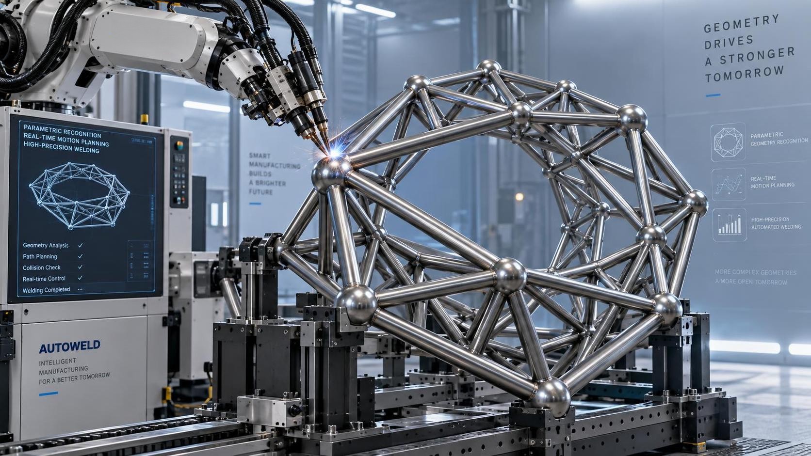
Yes—an automatic space frame welding machine can handle custom truss geometries without full reprogramming—but only if its control architecture separates geometry definition from motion logic. The critical distinction lies not in whether reprogramming occurs, but where and how much human intervention is required between design input and weld execution. At the core of this capability is parametric geometry recognition: the system interprets dimensional inputs—such as chord lengths, node angles, strut offsets, and spatial plane rotations—not as fixed coordinates, but as interdependent variables governed by constraint rules. When a new truss configuration arrives—say, an asymmetric octagonal canopy with varying bay depths and non-orthogonal support planes—the machine does not require rewriting G-code or resetting axis limits. Instead, it recalculates joint trajectories using real-time kinematic solvers that respect mechanical boundaries: maximum articulation range of welding torches, minimum clearance between adjacent members during positioning, and thermal distortion allowances based on material thickness and grade.
This responsiveness hinges on three integrated layers: a geometric abstraction layer that accepts CAD-derived node-and-member data (e.g., .dxf or .stp with embedded metadata), a motion planning layer that maps those nodes to physical tool paths while respecting collision envelopes and servo acceleration profiles, and a calibration layer that dynamically compensates for thermal drift and mechanical backlash without interrupting cycle flow. Crucially, none of these layers rely on hard-coded sequences. A change in flange width or web taper on a supporting H-beam member—common when integrating space frames into hybrid steel structures—does not trigger a cascade of manual edits. Rather, the system references stored rigidity models and adjusts feed rates, arc voltage, and dwell time per joint based on cross-sectional moment of inertia and heat sink capacity. That same adaptive logic extends to surface preparation: if galvanized coating thickness varies across incoming members, the plasma pre-cleaning module auto-adjusts dwell duration and power density to ensure oxide removal without zinc vaporization or base metal oxidation.
However, this flexibility has defined operational boundaries. It assumes consistent material delivery tolerances—specifically, that chord straightness deviation remains within ±0.3 mm/m and angular misalignment at node interfaces stays below 0.15°. Exceeding these thresholds forces the vision-guided seam tracking system to interpolate beyond its confidence envelope, risking incomplete fusion or excessive reinforcement buildup. Similarly, parametric adaptation presumes uniform joint topology: all connections must follow one of the supported configurations—single-shear gusset, double-plate splice, or welded spherical node—with no mixed-type junctions introduced mid-batch. Introducing a bolted connection alongside welded ones within the same truss segment breaks the continuity of the welding sequence logic and requires explicit operator confirmation before proceeding.
Integration with upstream and downstream equipment further defines practical scope. For instance, when feeding directly from an H beam 3D drilling machine, the automatic space frame welding machine receives not just part numbers but verified hole position data—including actual measured deviations from nominal coordinates—allowing it to offset torch paths accordingly. This closed-loop feedback eliminates cumulative tolerance stacking: if the YK-BHD1250 drills flange holes 0.22 mm left of center due to clamping force variation, the welding unit compensates in real time rather than assuming theoretical alignment. Such interoperability depends on synchronized coordinate system registration across both machines—requiring shared datum definitions (e.g., origin at left-end flange corner, Z-axis aligned with web centerline) and time-stamped metrology logs exchanged via OPC UA—not just generic file handoff.
Material behavior also governs what “no reprogramming” truly means. High-strength steels like S460ML demand tighter thermal management than S235JR: peak interpass temperature must stay below 250°C, and cooling rate between passes must exceed 1.5°C/s to avoid brittle phase formation. An automatic space frame welding machine meeting this requirement doesn’t simply reduce amperage—it modulates shielding gas composition (shifting from pure CO₂ to 75% Ar / 25% CO₂), activates pulsed current mode with variable peak/background ratios, and triggers forced-air cooling jets at precisely calculated intervals post-weld. These adjustments are embedded in material-specific process templates, not hardcoded routines. Switching from carbon steel to weathering steel isn’t a configuration toggle; it’s a controlled transition across multiple subsystems, validated through pre-weld test runs on scrap material cut to identical section properties.
Finally, verification remains inseparable from execution. “No reprogramming” does not mean “no validation.” Every new geometry triggers an automated dry-run simulation: the CNC axes traverse the full path at reduced speed while laser displacement sensors monitor structural deflection of the fixture table and gantry. If measured flex exceeds 0.08 mm at any point, the system flags the configuration for manual review—either adjusting clamp locations or modifying sequencing order to balance load distribution. This step prevents catastrophic collisions or positional inaccuracy that could otherwise go undetected until first weld deposition. The result is not blind automation, but traceable, physics-informed adaptability—where geometry changes drive recalculated constraints, not rewritten instructions.
search
Products Navigation
Send Us A Message