




What maintenance intervals are required for servo-driven positioning systems on an automatic space frame welding machine?
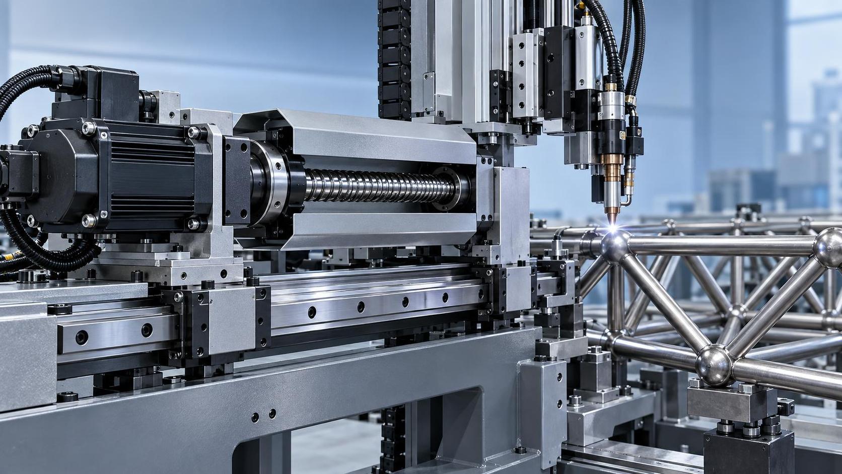
Maintaining optimal performance and longevity of an Automatic space frame welding machine hinges on precise, timely servicing of its servo-driven positioning systems. These systems—comprising servo motors, precision gearheads, ball screws, linear guides, encoders, and motion controllers—operate under high dynamic loads, rapid acceleration/deceleration cycles, and thermal fluctuations inherent to robotic welding environments. Unlike general-purpose servo applications, space frame welding demands micron-level repeatability across multi-axis coordinated motion, where even minor backlash accumulation or encoder drift directly compromises joint geometry, weld penetration consistency, and structural integrity of load-bearing chassis components.
Daily Visual & Functional Checks
Each operational shift begins with a visual and functional verification—not as routine formality, but as early anomaly detection. Inspect for abnormal vibration signatures near motor mounts or gearhead housings; listen for high-frequency whine or intermittent clicking during axis homing, which may indicate bearing preload loss or encoder signal dropout. Verify that all emergency stop circuits remain responsive and that brake engagement is immediate upon power interruption. Confirm vacuum adsorption stability on workholding fixtures—since unstable part registration induces compensatory servo corrections that accelerate wear on positioning actuators. A single missed daily check can mask developing issues such as micro-fractures in coupling elastomers or subtle misalignment between motor shafts and lead screws—both of which escalate into positional error exceeding ±0.15 mm within 72 operating hours.
Weekly Lubrication & Fastener Verification
Lubrication intervals are not calendar-based but condition-dependent: grease replenishment frequency correlates directly with ambient particulate exposure and duty cycle intensity. In facilities where metal dust from adjacent processes (e.g., laser cutting or plasma beveling) infiltrates the machine envelope, weekly re-greasing of linear guide rails and ball screw nut assemblies is mandatory—even if manufacturer specifications suggest biweekly intervals. Use only ISO VG 68 synthetic grease with EP additives and NLGI #2 consistency; over-lubrication traps abrasive particles, accelerating rail pitting. Simultaneously, torque-check all mounting bolts securing servo motor flanges, gearhead housings, and encoder couplings using calibrated tools—not estimated hand-tightening. Loosened fasteners induce phase lag between commanded and actual position, triggering servo alarm codes that falsely appear as controller faults rather than mechanical slippage.
Quarterly Encoder Calibration & Backlash Compensation
Encoder calibration must occur every 90 days—or after any mechanical intervention affecting axis kinematics (e.g., replacement of a ball screw assembly or realignment of a gantry beam). This process involves executing a full-axis bi-directional positioning sequence across at least five reference points per travel range, recording actual vs. commanded positions, and updating the motion controller’s backlash compensation table. Critical nuance: calibration data becomes invalid if performed without first verifying thermal equilibrium—meaning the machine must operate for ≥45 minutes at nominal load before measurement. Skipping this step introduces temperature-dependent offset errors that manifest as inconsistent weld seam deviation on thick-section nodes. Also inspect encoder cable shielding continuity: damaged braiding or compromised ground connections generate electromagnetic noise that corrupts quadrature signals, causing erratic position jumps indistinguishable from servo tuning instability.
Biannual Gearhead Oil Analysis & Motor Winding Inspection
For servo gearheads rated above 10 N·m output torque, oil analysis every six months is non-negotiable. Extract 5 mL sample from the drain port after a minimum 30-minute runtime at operating temperature. Lab testing must include ferrography (to detect early-stage gear tooth fatigue spalling) and viscosity drift assessment. A 15% viscosity drop indicates thermal degradation compromising hydrodynamic film formation—leading to micropitting that progresses to catastrophic gear failure within 200–300 additional operating hours. Concurrently, perform insulation resistance testing on servo motor windings using a 500 V DC megohmmeter. Values below 5 MΩ warrant immediate disassembly—moisture ingress or winding abrasion often occurs where cable conduits flex repeatedly near robot joints, not at the motor housing itself.
Annual Mechanical Reconditioning
Annual reconditioning goes beyond lubrication—it addresses cumulative mechanical hysteresis. Disassemble and inspect ball screw return tubes for plastic deformation caused by repeated impact loading during rapid deceleration. Replace linear guide carriages showing >0.02 mm radial play in recirculating ball channels, even if still within OEM tolerance bands: such play permits transient axis deflection during high-current weld initiation pulses, degrading arc stability. Recalibrate all proximity sensors used for soft-limit detection; their magnetic field attenuation over time shifts trip points by up to 1.2 mm, risking unintended collision responses. Crucially, verify that servo amplifier current loop gains remain matched across axes—drift exceeding ±3% between X/Y/Z amplifiers creates unbalanced torque distribution during synchronized motion, accelerating wear on specific bearings while masking underlying imbalance through adaptive control algorithms.
These intervals reflect field-proven thresholds—not theoretical limits. For example, in high-mix production where space frame geometries vary significantly (e.g., switching between automotive subframes and architectural trusses), encoder recalibration frequency increases to every 60 days due to differential thermal expansion coefficients across dissimilar materials. Similarly, when processing aluminum alloys with high thermal conductivity, gearhead oil change intervals shorten by 30% compared to steel-only operations, as localized heating accelerates oxidation. Precision deburring prior to welding also affects positioning system longevity: burr-induced part misregistration forces continuous servo correction, increasing heat generation in motor windings by up to 18% over baseline conditions. Equipment like the RNS 800 Sheet metal deburring machine, capable of removing laser-cut and plasma-cut burrs while forming consistent R-angles, directly reduces this correction load by ensuring dimensional fidelity before clamping. Ultimately, maintenance timing must respond to measurable parameters—not fixed schedules—because servo-driven positioning systems degrade along multiple concurrent pathways: mechanical, thermal, electrical, and environmental. Ignoring any one pathway invalidates the entire interval framework.
search
Products Navigation
Send Us A Message