




Can sheet metal deburring equipment remove laser-cut oxide layers?
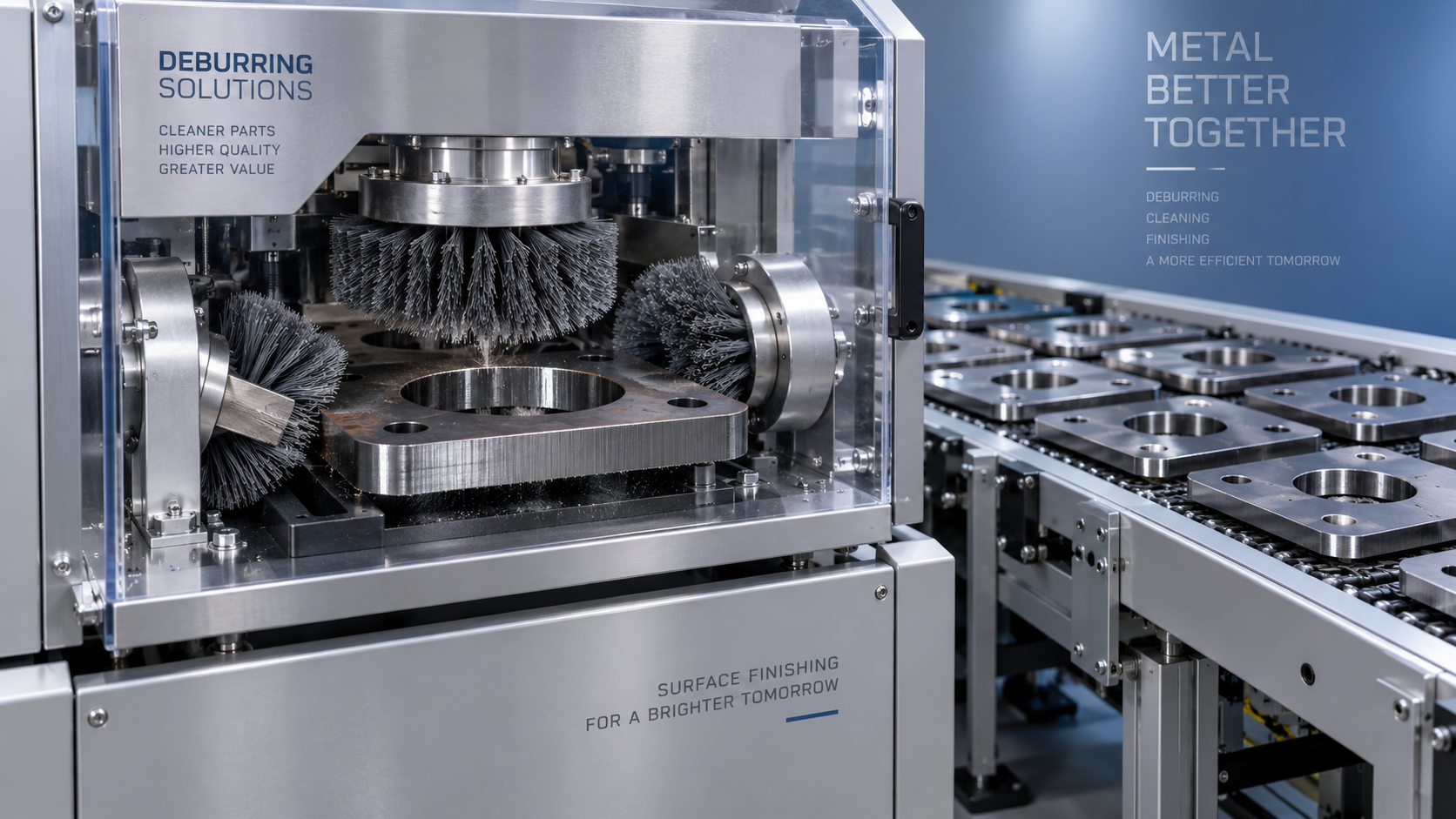
Can sheet metal deburring equipment remove laser-cut oxide layers?
Yes—sheet metal deburring equipment can remove laser-cut oxide layers, but only when its tooling and process settings are suited to edge cleaning rather than burr removal alone. The key question is whether abrasive brushes or other suitable tools can reach the cut edges and remove oxide consistently without excessive rounding or dimensional change. Material type, cutting gas, part geometry, and abrasive selection all affect the result—and whether the part is ready for welding, coating, or assembly.
A machine that leaves a smooth top surface is not necessarily cleaning the vertical cut face. That distinction is easy to miss during a demonstration, especially when the sample is a simple rectangle rather than a production part with narrow slots and internal contours.
Burr removal and oxide removal are different jobs
Laser-cut parts can carry several conditions at once: attached dross near the bottom edge, sharp corners, striations along the cut face, and an oxide layer produced during cutting. These conditions occupy different locations and respond differently to abrasion.
An abrasive belt can remove protruding burrs efficiently because they stand above the surface being processed. Oxide on a vertical edge may sit below the belt’s direct contact area. Removing it requires tooling that engages the cut face, not simply tooling that levels the sheet surface.
Edge rounding is also not proof of oxide removal. A brush may soften the upper and lower corners while leaving oxide in the middle of a thicker cut face. Conversely, aggressive edge cleaning may remove oxide but create an unacceptable radius on a locating feature. Both cleanliness and geometry need their own acceptance criteria.
Start with the material and cutting gas
Oxygen-assisted laser cutting of carbon steel normally produces an oxidized cut edge. This is the most straightforward application for evaluating mechanical oxide removal. The cleaning difficulty depends on the actual cut quality, plate thickness, and accessibility of the edge—not just the material designation.
Nitrogen-assisted cutting generally limits oxidation during cutting, provided gas purity and process conditions are suitable. It does not guarantee a contamination-free part: burrs, handling oils, and surface deposits may still require attention. Air-assisted cutting can also produce oxidation because air contains oxygen, although results vary with the cutting setup.
Stainless steel requires a different discussion. Mechanical brushing can remove visible discoloration or oxide, but a bright-looking edge does not establish restored corrosion performance. Applications with corrosion requirements may need qualified pickling or passivation procedures, depending on the material, surface condition, and project specification. Avoid transferring carbon-steel contamination through shared tooling or handling equipment.
Aluminum should not be treated as an equivalent carbon-steel application. Its oxide reforms readily, and abrasive cleaning must be coordinated with welding preparation and storage practices. Mixed-material processing also introduces dust-management questions that should be reviewed with the equipment supplier before a common extraction system is selected.
Which machine configurations can reach the oxide?
Look at the working heads rather than the machine’s general “deburring” label. Some systems are configured primarily for flat-surface finishing; others combine burr removal with multidirectional edge brushing. Their capabilities are not interchangeable.
Flexible abrasive filaments or strips can follow contours, but flexibility alone does not guarantee effective cleaning. Tool stiffness, abrasive type, contact angle, and penetration determine whether the tool removes oxide or merely polishes its outer surface. Ask the supplier to identify the proposed tooling and explain where it contacts the part.
For narrow slots, small holes, deep profiles, or thick plate, a conveyor-fed brush system may leave inaccessible areas. Secondary treatment—or a change to the upstream cutting process—may be more practical than increasing pressure until the exposed edges are overprocessed.
The process window matters as much as the hardware
Feed speed, tool speed, engagement depth, abrasive grade, and pass count work together. Slower feeding increases exposure, but also increases the opportunity for stock removal, heating, and edge rounding. More pressure is not a universal answer; excessive engagement can distort thin parts, accelerate tool wear, or undermine part retention.
Thickness variation and flatness deserve attention. A recipe that works on flat coupons may behave differently on bowed sheets or parts with residual cutting stresses. Small components need suitable hold-down arrangements, with minimum part dimensions confirmed for the proposed configuration. Vacuum or magnetic retention should be evaluated against the actual material and geometry.
Tool wear changes the process window. A successful trial with new brushes says little about performance near the replacement point. Request evidence of repeatability as tools wear, along with the adjustment method and replacement criterion. Otherwise, operators may compensate for declining cleaning action with settings that gradually push dimensions outside tolerance.
Define “clean enough” through the next operation
For powder coating or painting, residual oxide can become a weak interface. The relevant question is whether the coating system adheres to the prepared edge—not whether the uncoated part looks attractive. Run the intended pretreatment and coating sequence on trial parts, then assess adhesion using the project’s specified method. Mechanical deburring does not replace degreasing or other required pretreatment.
For welding, preparation should follow the qualified welding procedure or applicable production requirements. Oxide and other contamination can contribute to weld defects, but removing them does not eliminate issues caused by joint fit-up, shielding, or welding parameters. Check the surfaces that actually enter the joint rather than assuming the visible perimeter represents the entire weld preparation.
This distinction remains important in automated fabrication. Wuxi Samgins International Trade Co.,Ltd supplies both deburring equipment and welding systems, including the 7 axis cantilever type welding robot for long steel workpieces. Its seven CNC axes and automatic seam tracking address welding motion and joint following; they do not substitute for clean joint surfaces. A linked production plan should therefore define edge preparation, fit-up, and robotic welding requirements separately.
For assembly, inspect features where material removal matters: locating tabs, slot widths, bearing interfaces, and sealing edges. A clean edge that no longer fits is not an acceptable result.
Make the acceptance trial representative of production
Send actual laser-cut parts rather than hand-selected easy samples. Include the material grades, thicknesses, gases, and geometries that define the difficult end of your normal workload. Keep untreated reference parts so changes in cut quality are not confused with changes in machine performance.
- Inspect external edges, internal contours, and the middle of the cut face—not just the top corner.
- Agree on an inspection method for residual oxide; visual assessment alone may be insufficient for demanding applications.
- Measure critical dimensions and edge radii before and after processing.
- Record tooling, settings, pass count, part orientation, and whether flipping is required.
- Evaluate coated or welded samples through the intended downstream process.
- Run a sequence of parts to check retention, handling, repeatability, and tool loading.
Photographs are useful records, but lighting can make a partially cleaned edge look uniformly bright. Where necessary, use magnified inspection or another agreed method to distinguish remaining oxide from normal cut-face texture. Acceptance limits should be documented before the demonstration, not negotiated after seeing the result.
Choose around verified edge quality, not nominal throughput
Compare sheet metal deburring equipment using the complete route: loading, cleaning passes, flipping, inspection, and any secondary treatment. Conveyor speed alone can conceal substantial handling time. Consumable life, brush availability, extraction requirements, and changeover between materials also affect the usable production capacity.
Established in Wuxi in 2012, Wuxi Samgins International Trade Co.,Ltd supplies cutting, forming, deburring, and welding machinery to domestic and overseas markets. That equipment range provides a useful basis for discussing the whole fabrication sequence. For a specific purchase, however, request machine-level technical documentation, applicable conformity records, spare-tool provisions, and acceptance-test commitments rather than relying on general company credentials.
The practical decision is conditional: choose mechanical oxide removal when the tools can reach every required edge, preserve tolerances, and pass downstream checks. If inaccessible contours or excessive rounding prevent that result, reconsider the cleaning method or cutting gas. The next step is a documented sample trial with clear cleanliness, geometry, and production-rate limits—not simply a demonstration of a smoother-looking part.
search
Products Navigation
Send Us A Message