




Do Welding Robots Need Dedicated Fixtures for Every Part Shape?
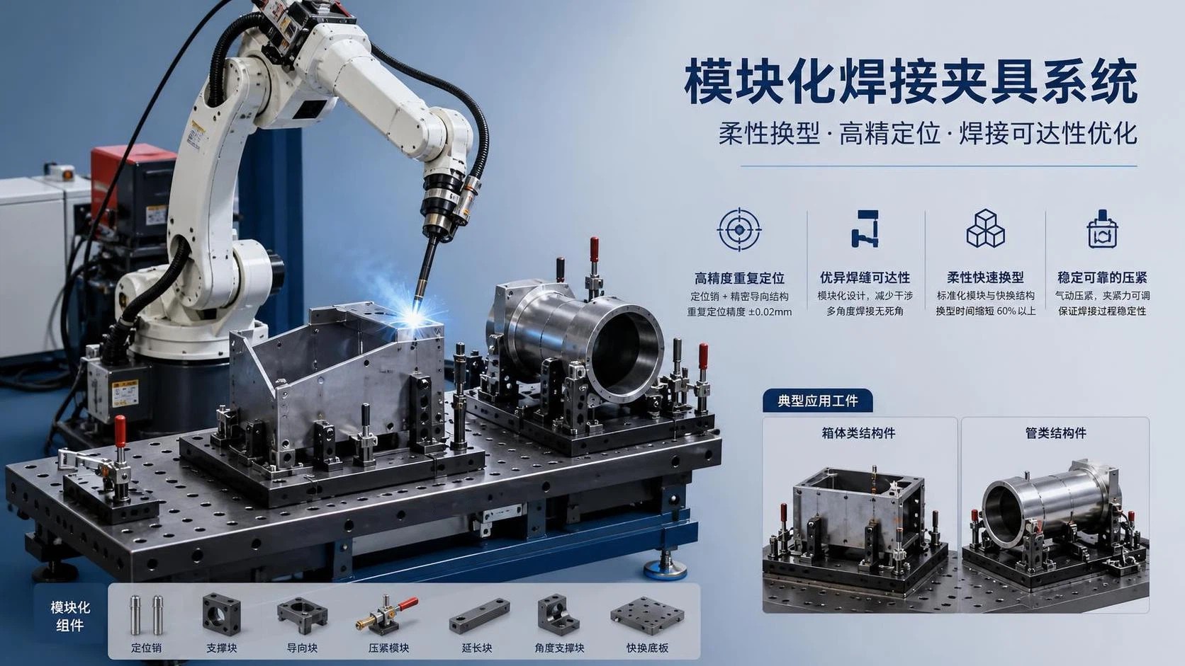
Usually, no. A welding robot does not automatically need a dedicated fixture for every different part geometry. The real requirement is stable and repeatable part location at the weld joint. If a fixture can place several part variants within the robot's programmed tolerance window, a shared or modular fixture may work well. If part shape changes alter joint position, gap, angle, or heat distortion behavior too much, then a dedicated fixture becomes hard to avoid.
This distinction matters because robotic welding is less tolerant of variation than many manual operations. A skilled welder can compensate for a slightly shifted edge, a wider root gap, or a flange pulled out of square after tack welding. A robot follows taught points or path data. Unless the cell includes seam tracking, touch sensing, vision correction, or adaptive programming, the torch will still move to the same coordinates even when the actual joint has moved. In practice, fixture choice is tied to the allowable variation of the part, not only to its overall shape.
What the fixture is really doing
In robotic welding, the fixture is not just a holding device. It establishes datums, resists movement during clamping, controls distortion during welding, and presents the joint to the torch at a reachable angle. For fillet welds on carbon steel brackets, that may be straightforward: two locating pins, a stop block, a pneumatic clamp, and adequate clearance for the gun neck. For a stainless enclosure with long seam welds, thermal movement and cosmetic requirements may force a much more controlled setup, including copper backing, segmented clamps, and a sequence that manages shrinkage between passes.
When asking, “Do welding robots require special fixturing for each different part geometry?”, the more useful question is often narrower: which geometric differences actually change weld execution? A part may look different on paper yet still share the same reference planes, same joint line, and same torch access. In that case, one fixture base with changeable nests or locator blocks may be enough. Another pair of parts may appear similar, but one has a gusset that blocks the torch approach, or a tab position that shifts the seam by a few millimeters. Those small differences can force a different fixture concept.
Cases where a dedicated fixture is often justified
Dedicated fixturing becomes more likely when the weldment has tight dimensional tolerances after welding, when the assembly sequence is sensitive, or when the part has a geometry that reacts strongly to heat. Thin sheet components are a common example. A robot can weld them consistently, but only if the fixture controls fit-up and prevents local lifting. If the sheet thickness, flange length, or bend springback changes from one model to another, a universal fixture may lose enough control to affect bead placement or distortion.
Pipe and tube fabrications create another boundary. Round parts tend to rotate, ovality can vary, and cut-end preparation may not be perfectly consistent after sawing or laser cutting. If one tube frame uses 40 mm square tube and another uses 60 mm rectangular tube with different node angles, the clamping points, support heights, and torch access windows may need a dedicated arrangement. Even when the robot can be reprogrammed, the fixture still has to stop the assembly from creeping during tack and weld cycles.
Heavy structural parts can also justify dedicated fixtures, though for a different reason. The issue may not be fine-position accuracy alone, but stiffness and load path. A weldment made from thick plate, H-beam sections, or machined components can place significant force on clamps and locators. If fixture surfaces deflect under load or under repeated loading cycles, repeatability drops. In such cases, a robust fixture designed around one family of parts may be safer than a highly adjustable system with many bolted interfaces.
- A joint that must remain within a narrow positional tolerance because the robot uses fixed taught points with limited sensing.
- Parts whose geometry changes block the torch angle, nozzle clearance, or cable routing in a way that cannot be solved with minor locator changes.
- Assemblies where clamping sequence directly affects final distortion, especially on thin wall material, long seams, or asymmetric weld patterns.
- Workpieces with enough mass or leverage that a generic fixture frame may flex or wear faster than expected.
When modular fixturing is a better answer
Modular fixturing works best when parts belong to a true family rather than a loose collection of unrelated drawings. A part family may share the same base datum, similar material thickness, comparable weld joint style, and common loading direction. In that situation, the fixture can use a standard base plate, grid holes, replaceable nests, adjustable stops, and quick-change clamps. The robot program can then switch between recipes while preserving a known coordinate system.
That approach is common in shops handling medium-volume fabrication where batch sizes change frequently. The value is not only lower tooling cost. Changeover time, floor space, and maintenance effort also matter. Ten dedicated fixtures for ten low-volume parts may consume more storage and setup attention than one modular platform with documented locator positions. However, modular does not mean loosely adjustable in a trial-and-error way. If operators have to shim parts manually or “fine tune” stops each shift, the fixture is no longer delivering robotic-level repeatability.
There is also a practical middle ground: a dedicated fixture body with interchangeable contact elements. This is often useful when the part envelope stays similar but one or two features move. For example, a fabricated bracket may keep the same main plate and side wall while hole patterns or tab locations vary by model. Replaceable locator pins, stop fingers, or clamp pads can accommodate those variants without redesigning the entire fixture. That is still specialized fixturing, just not one complete fixture per drawing.
Joint quality matters more than outer contour
Many people focus first on part outline, but the robot only cares about the weld joint and how consistently the torch can reach it. Two parts with very different external profiles may weld fine in the same cell if the joint line is presented in the same position and orientation. On the other hand, two almost identical frames may need different fixturing if one uses a lap joint and the other uses a corner joint with a tighter gun angle.
Material condition also changes the answer. Hot-rolled steel with mill scale, laser-cut parts with varying edge oxidation, galvanized components, and aluminum with oxide layer buildup do not behave the same during welding. If the process window is already narrow because of surface condition or fit-up sensitivity, fixturing has less room for error. A modular fixture may still work, but it may need better part seating, stronger clamping, or added sensing routines.
For aluminum in particular, thermal expansion and part cleanliness often expose fixture weaknesses quickly. Soft contact surfaces can wear, locating points may pick up debris, and the assembly may move as heat accumulates. Stainless parts may bring a different issue: heat tint and cosmetic appearance can make clamp marks, backside support, and weld sequencing more important than on ordinary carbon steel fabrication.
Fixture design has to match the welding process
MIG robotic welding is often more forgiving of small gap variation than TIG, but that does not remove the need for accurate location. If pulse MIG is used on thin sections, the process may tolerate some variation while still requiring stable torch stand-off and clean approach. Tandem or higher-deposition processes can increase heat input and make restraint more critical. Spot welding, laser welding, and arc welding each place different demands on fixture rigidity and accessibility, even when the same part geometry is involved.
Positioners further complicate the decision. A part that seems to require a dedicated fixture in a flat, fixed table setup may become easier to standardize if a servo positioner can rotate it into a common weld orientation. Conversely, once a part is mounted to a headstock-tailstock setup, balance, centerline, and collision envelope may force a dedicated mount. The fixture is part of the motion system, not an isolated accessory.
Common misjudgments during planning
One frequent mistake is assuming that programmable robots can absorb fixture variation through software alone. Offline programming, torch touch sensing, or vision can correct some positional errors, but they do not replace poor part restraint. If a component lifts when clamped, shifts under thermal stress, or arrives with inconsistent cut quality, the robot may still produce unstable welds or lose cycle time in repeated searches.
Another mistake is designing a universal fixture around maximum adjustability instead of repeatability. Sliding rails, multiple slotted brackets, and hand-set locators can look flexible during design review, yet become difficult to lock precisely on the production floor. After several changeovers, wear, spatter buildup, and operator variation may reduce accuracy. A more disciplined modular system usually relies on defined hard stops, doweled change parts, and documented setups rather than infinitely adjustable features.
There is also a tendency to underestimate loading and unloading. If a fixture can technically hold five part families but requires awkward loading around clamps and torch clearance pockets, practical throughput may suffer. The robot may spend less time welding than the operator spends positioning parts. In some cells, a simpler dedicated fixture with fast access produces smoother flow than a universal fixture with too many compromises.
Maintenance and wear affect the fixture decision
Fixtures in welding cells live in a harsh environment. Spatter accumulates on contact points, clamp cylinders lose consistency over time, anti-spatter compounds attract dirt, and repeated heating can alter small details that matter to part seating. A modular fixture with many replaceable elements can be easier to maintain if those wear points are standardized. It can also become harder to maintain if the system has too many small parts and no clear inspection routine.
Locating pins, rest pads, and clamp faces should be selected with actual wear patterns in mind. Hardened steel inserts may be appropriate for repeated loading of machined parts. Softer contact materials may be preferred where cosmetic marking matters. If stainless contamination must be avoided, tooling materials and cleaning practice may need more attention. These details influence whether a shared fixture remains stable across multiple geometries or slowly drifts out of useful tolerance.
Transport, installation, and upstream process variation also matter
Parts do not arrive in the welding cell as perfect CAD models. They come from cutting, bending, machining, rolling, or previous tack operations, and each upstream step adds variation. Plate cut on one machine may have a slightly different edge condition from plate cut on another. Press brake springback can shift flange angle. Long parts may deform during storage or transport on pallets if stacking support is poor. A fixture strategy that looks adequate during sample evaluation may struggle once normal shop variation appears.
Installation conditions matter as well. Floor flatness, positioner alignment, utility routing, and access for maintenance influence fixture performance. A large fixture that is difficult to realign after removal may not be ideal for a mixed-production line. In some installations, repeatable docking to a common base is more valuable than making the fixture itself highly adjustable.
A practical way to decide
The most reliable test is to map the real variation that reaches the weld joint. Measure where the joint lands relative to chosen datums across sample parts, not only nominal dimensions from drawings. Note gap range, angular error, edge condition, and deformation after clamping. Then compare those values with process tolerance, torch access, and sensing capability. If several geometries still place the weld in nearly the same location and orientation, shared fixturing is realistic. If they do not, forcing them into one fixture often creates hidden cost in debugging and downtime.
So, do welding robots need dedicated fixtures for every part shape? No, but they do need fixturing that makes each weld joint predictable. Sometimes that means one dedicated fixture per part. Sometimes it means a modular platform with controlled change parts. The deciding factor is not the number of shapes on the drawing list. It is whether the robot can meet the joint consistently, under production conditions, with stable loading, acceptable distortion, and maintainable tooling.
search
Products Navigation
Send Us A Message