




How to Select an Industrial Handling Robot Arm for Payload, Reach, and Cycle Time?
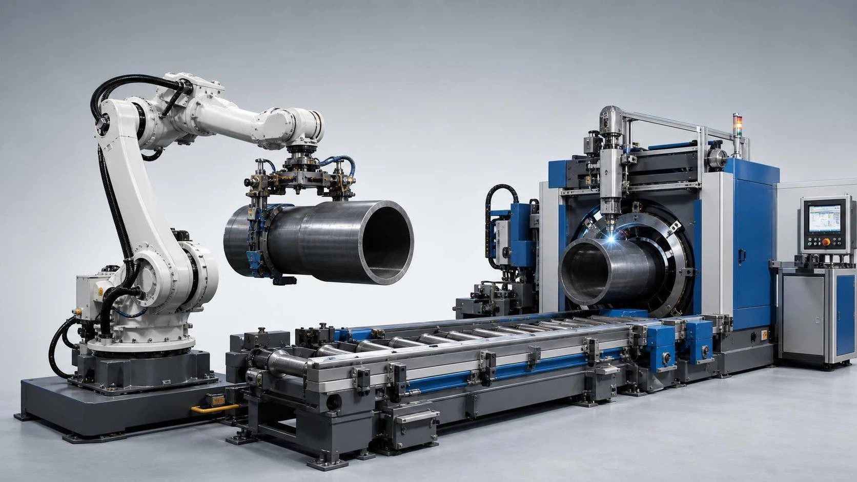
Selecting an industrial handling robot arm is rarely a matter of choosing the largest payload figure on a catalog page. In a real production cell, the robot must pick a part reliably, clear fixtures and guarding, orient the part without collision, place it accurately, and repeat the sequence for thousands of cycles. A robot that looks adequate on paper can become a bottleneck if its usable reach is too short, its wrist load is underestimated, or its motion profile cannot meet the required takt time.
For technical evaluators, the most useful question is not “Which robot has the highest specification?” It is: “Which robot can complete this exact handling task safely and consistently, with reasonable integration risk?” The answer comes from connecting payload, reach, cycle time, end-of-arm tooling, layout, and process conditions into one assessment.
Start with the part journey, not the robot catalog
Before comparing robot models, map the physical journey of the workpiece. Identify where the part begins, how it is presented, where it must be delivered, and what orientation changes occur along the way. This sounds basic, yet it is where many selection errors begin.
A handling cycle may include picking from a pallet, separating nested parts, lifting from a conveyor, rotating for inspection, loading a fixture, waiting for a machine signal, unloading the finished piece, and stacking it in a defined pattern. Each movement changes the required robot envelope and the load seen at the wrist.
Document the following items for every pick-and-place point:
- Part dimensions, mass, center of gravity, and permitted gripping surfaces
- Part temperature, surface condition, sharp edges, oil, scale, or weld spatter
- Pickup and drop-off coordinates, including height and approach direction
- Required part orientation at each station
- Fixture, machine door, conveyor, safety fence, and operator access restrictions
- Whether the robot must reach into a machine or around an obstruction
- Production rate, buffer capacity, and the effect of an occasional missed cycle
A CAD layout, even a preliminary one, is far more valuable than relying on nominal reach dimensions alone. The outer edge of a robot’s working envelope is not always a productive zone. Axis limits, singularities, tool angles, cable routing, and collision clearance can make the theoretical maximum reach impractical for routine operation.
Payload is a system calculation
The stated payload of an industrial handling robot arm refers to more than the workpiece. The robot wrist must carry the entire end-of-arm system: gripper, adapter plate, sensors, pneumatic valves, cabling, tool changer, protective covers, and the part itself. If a robot is used for dual picking or carries a fixture during a transfer operation, those components must be included as well.
A practical payload estimate can be expressed as:
Total moving load = part mass + gripper mass + tool interface + sensors/cables + retained material or process accessories.
That total must then be assessed together with the load’s center of gravity and inertia. A compact 20 kg component held close to the robot flange may be easier to move than a lighter but long, offset tube gripper. Long tools create a greater wrist moment. A load with a distant center of gravity can reduce available speed and acceleration, affect path stability, or exceed axis limits even when the nominal payload number appears acceptable.
Do not assume that adding a small safety margin solves every issue. The appropriate margin depends on the application. Stable, rigid metal components may be predictable, while castings with dimensional variation, parts with residual liquid, or packages that shift during acceleration require more caution. For high-duty applications, request the manufacturer’s load diagram and verify the proposed center-of-gravity coordinates against the specific robot model.
Questions worth asking during payload review
- Is the quoted robot capacity available at the required wrist orientation and reach?
- Does the gripper weight include hoses, connectors, mounting brackets, and cable dress-out?
- Will the load change during the cycle, such as when picking one part from a stack or two parts at once?
- Can the robot control identify a failed pick before the part enters a machine or fixture?
- Will future product variants require a heavier gripper or a different tool?
Choosing too close to the payload limit may not cause an immediate failure; the more common consequence is a system that must be slowed down, tuned conservatively, or maintained more frequently than planned.
Reach must be evaluated in three dimensions
Robot reach is often described as the maximum distance from the base to the wrist center. This specification is useful for initial filtering, but it does not confirm that the robot can perform the application. A handling robot needs usable reach at the correct height, angle, and orientation.
Consider a robot loading a press brake or CNC machine. It may need to approach vertically above a locating fixture, lower the part without touching clamps, release it, retract along a safe path, and then swing clear of the door zone. The critical point is not the farthest point on the table; it is the most restrictive position along the approach path.
Base location has an equally strong influence. Moving the robot base by a few hundred millimeters can improve reach symmetry, shorten travel distance, and reduce awkward wrist configurations. In some cells, a pedestal-mounted robot offers better access over a conveyor. In others, an inverted or rail-mounted arrangement creates a more efficient envelope. These options should be compared before selecting a larger arm simply to compensate for a poor layout.
Long parts deserve particular attention. When handling pipe, beams, sheets, or fabricated assemblies, the robot may require coordinated movement with a second robot, a positioner, support rollers, or a gantry. A single arm may be sufficient for positioning a short component, but it should not be assumed capable of controlling a long, flexible workpiece safely at one end.
Cycle time is not the robot’s published speed
Manufacturers may list maximum joint speeds or a standard cycle benchmark, but neither number represents the cycle time of a specific handling cell. Actual throughput includes gripping, sensing, path transitions, machine interlocks, door operation, vision processing, safety-zone coordination, settling time, and release confirmation.
Build the cycle from events rather than from an optimistic motion estimate:
- Receive the ready signal and confirm the pickup location.
- Move to the approach point.
- Enter the pickup position, close the gripper, and confirm part presence.
- Retract and travel to the machine, fixture, pallet, or downstream station.
- Approach, place, release, and verify the drop-off condition.
- Exit safely and synchronize with the next process step.
The robot’s contribution is only one portion of this timeline. If a welding process takes several minutes, a few extra seconds of robot travel may have little effect on output. If the robot services multiple high-speed machine tools, however, minor delays can accumulate into lost spindle utilization. The correct selection therefore depends on the production bottleneck.
Acceleration capability matters as much as top speed. Heavy payloads and extended tools require smooth acceleration and deceleration to prevent part movement, fixture impact, or excessive vibration. A cell tuned for the shortest theoretical cycle may be less stable than one that uses controlled corner transitions and predictable settling. During acceptance planning, define the required sustained cycle time, not merely a best-case demonstration cycle.
Accuracy, repeatability, and the fixture reality
Technical specifications frequently emphasize repeatability, which is the robot’s ability to return to a programmed position. This is important, but it should not be confused with absolute accuracy. A robot can repeat a position very well while the actual part location varies because of a pallet shift, inconsistent incoming material, thermal changes, or fixture tolerance.
For simple transfer operations, mechanical guides and robust fixtures may be enough. For mixed-part loading, variable castings, or loosely presented workpieces, vision guidance, force sensing, or compliance devices may be needed. The goal is not to add technology unnecessarily; it is to match the locating strategy to the actual variation in the process.
Gripper design deserves the same discipline as robot selection. A well-chosen gripper should provide secure retention, tolerate reasonable part variation, allow sensor confirmation, and release cleanly. Vacuum tooling may be suitable for flat sheet material but can be unreliable on porous, oily, perforated, or warped surfaces. Magnetic gripping is effective for many ferrous parts, though residual magnetism, surface scale, and safe release must be considered. Mechanical clamping may offer the highest security for irregular components, often at the cost of a more complex tool and longer engagement time.
Use the production environment to narrow the robot family
The operating environment changes what “reliable” means. In metal fabrication, robots may work near grinding dust, cutting fluid, weld fumes, heat, or spatter. In food, medical, and clean manufacturing, washdown requirements and material selection become more important. Outdoor or foundry-related applications may require specialized protection and more conservative maintenance planning.
For welding-related handling, keep the robot’s task separate from the welding process when defining requirements. A robot that loads pipe sections, supports assemblies, or transfers finished components may need different protection, reach, and controller integration than a dedicated welding robot. The two systems can be coordinated, but they should be evaluated according to their own duty cycles and risks.
For example, a pipe fabrication line may use an automated welding system for the seam operation while a handling solution manages loading, unloading, staging, or part transfer. The 12 meter Pipe inside and outside seam welding machine is designed for batch production of small-diameter pipe, with pipe lengths up to 12 m, diameters from 400 to 1500 mm, and thicknesses from 6 to 20 mm. In this type of layout, the handling assessment should focus on how pipe sections are supported, indexed, and presented to the welding station—not simply on whether an arm can lift the nominal pipe weight.
Its adjustable trolley movement and welding monitoring functions also illustrate an important integration principle: robot motion must coordinate with process status. The material handling system should not advance a part until the welding sequence, inspection condition, and safe access state are confirmed by the cell controls.
Integration details that should be specified early
A robot arm is only one part of an automation system. Early discussions with the integrator, machine supplier, and production team prevent costly late changes. Define the communication method between the robot controller and connected equipment, including ready, busy, fault, safety, and part-identification signals. Clarify who owns the master sequence and how the cell behaves after a fault or emergency stop.
Also review practical matters that are easy to overlook during concept approval:
- Floor loading, anchoring, pedestal design, and vibration from nearby equipment
- Electrical supply, pneumatic capacity, vacuum generation, and air quality
- Space for controller cabinets, maintenance access, and teaching positions
- Safety fencing, interlocked doors, scanners, light curtains, and collaborative operation requirements
- Offline programming, simulation data availability, and changeover procedures
- Spare parts strategy, operator training, and local service support
For businesses sourcing machining, cutting, welding, and forming equipment from one supplier group, integration coordination can be especially valuable. Wuxi Samgins International Trade Co., Ltd. supplies a broad range of fabrication and machine-tool equipment, including welding automation, CNC cutting equipment, machine tools, and related production systems. When evaluating a robot cell alongside upstream or downstream equipment, ask for a layout and interface review rather than treating every machine as an isolated purchase.
A practical comparison method for technical evaluators
Shortlist two or three robot options that satisfy the basic load and reach envelope, then compare them against the same application data. Avoid scoring only headline specifications. A structured evaluation can include usable payload at the required center of gravity, coverage of all critical positions, estimated cycle performance, tool compatibility, environmental suitability, controller interfaces, serviceability, and allowance for future variants.
At this stage, simulation is valuable, but it should be treated as validation rather than decoration. Ask for verification of collision clearance, axis configurations, cycle assumptions, and recovery positions. If possible, test the real gripper and representative parts. A simulation based on simplified boxes may miss the behavior of flexible pipe, oily sheet, unstable stacks, or parts with difficult edges.
The best industrial handling robot arm is not necessarily the fastest or the strongest model in the comparison. It is the one that carries the complete tool-and-part load within its approved limits, reaches every required point without awkward motion, supports the production takt with stable trajectories, and fits into a maintainable, safe manufacturing cell. That is the standard worth using when the investment will be judged on daily output rather than catalog specifications.
search
Products Navigation
Send Us A Message