




Which motions matter in a handling robot arm for metal fabrication?
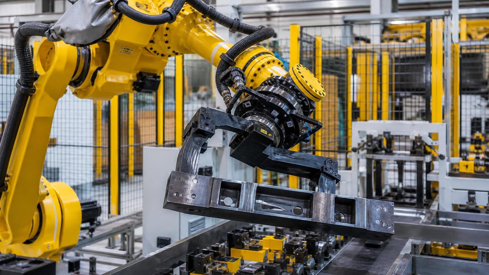
The motions that determine whether a robot arm will work on the shop floor
For a handling robot arm for metal fabrication, the most important motions are usually not the ones that look impressive in a specification sheet. A long reach or a high payload rating may be necessary, but stable production depends more directly on whether the arm can approach a part, control its orientation, clear surrounding equipment, and place it repeatably without consuming too much cycle time.
In most fabrication cells, four motion capabilities deserve early attention: base and shoulder travel for access, elbow motion for reach and clearance, wrist orientation for gripper control, and coordinated multi-axis movement for smooth transfers. Their relative importance changes with the part geometry, fixture design, process machine, and handoff points. A robot that is adequate for moving flat blanks between conveyors may be poorly suited to loading structural weldments, rotating pipe sections, or presenting beam ends to a machining station.
Technical evaluation should therefore begin with the motion required at the pick point, process point, and placement point. The robot must perform each position in the real layout, with the actual end effector and a realistic representation of the workpiece, rather than merely reach an idealized point in open space.
Base and shoulder motion define usable access
The first axes of an articulated arm carry most of the reach envelope. Base rotation allows the robot to serve multiple stations or move between an infeed rack and a machine door. Shoulder movement raises and lowers the arm and strongly affects its ability to reach into fixtures, over safety fencing, or across a conveyor.
These motions matter most when the cell has a wide working area or when a robot must service several machines. They also determine whether the robot can approach a part from a practical direction. A theoretically reachable location may still be unusable when the upper arm passes through a fence line, collides with a machine enclosure, or blocks an operator access path.
For metal fabrication, access is rarely a simple horizontal-distance problem. Sheet blanks may lie flat and low; fabricated frames may be staged upright; beam components may require the gripper to approach from above, from the side, or at an angle. The shoulder axis must have enough range to make these approaches without forcing the wrist close to a singular position or creating an overly extended arm posture.
Longer reach is not automatically better. As the arm extends, structural deflection, stopping behavior, cable movement, and sensitivity to payload inertia can become more significant. A shorter robot mounted closer to the equipment may deliver more consistent placement than a larger model working near the edge of its envelope. The preferred layout keeps the most accuracy-sensitive pick and place positions within a comfortable central portion of the robot workspace.
Elbow motion is often the clearance axis
The elbow axis is easily underestimated because it is commonly treated as part of the robot's overall reach. In fabrication cells, however, it often decides whether the arm can navigate around clamps, fixture posts, machine guarding, part nests, roller tables, and adjacent workpieces.
An arm may be able to place a part at the correct final coordinates yet fail during the path to that point. For example, a gripper carrying a bent sheet-metal component may need to enter a press brake area without the elbow sweeping into the machine frame. A robot loading a welding fixture may need to lower a component through a narrow opening before rotating it into the clamping position. Structural sections introduce the same issue at a larger scale: the part itself becomes a moving obstruction whose corners and overhangs must clear the cell.
This is why reach drawings alone are insufficient. The evaluation model should include the full swept volume of the arm, tool, cables, and part. It should also cover the robot's return path after release, since a collision-free insertion path does not guarantee an unobstructed exit.
Part families complicate the decision. If a cell handles only one well-controlled blank size, a tailored layout may be practical. If it processes variable beam lengths, profiles, fixtures, or assemblies, elbow flexibility has greater value. The robot should have enough alternative joint configurations to reach the same end position through different postures when the preferred route is blocked.
Wrist axes control the part, not just the tool
For handling applications, the wrist is frequently the most consequential part of the motion system. A six-axis robot typically uses three wrist axes to control roll, pitch, and yaw at the end effector. That flexibility allows the robot to keep a gripper level, rotate a component for downstream processing, align a profile with a locator, or maintain a required approach angle while the larger arm axes move around obstacles.
Wrist rotation becomes especially important when the part orientation must be preserved. A vacuum gripper handling a thin sheet may need to remain close to level to avoid part slip or bending. A magnetic gripper holding a structural plate needs enough clearance to release safely without dragging the part across locating surfaces. Fork, clamp, and mechanical grippers can introduce their own orientation limits, particularly when they engage holes, flanges, or irregular edges.
For welding and assembly cells, orientation accuracy has a direct effect on fit-up. A part may be delivered within the robot's stated positional repeatability yet still sit incorrectly if the wrist angle is inconsistent. Small rotational errors can become noticeable at the far end of a long component, at paired locating points, or when a component must meet a pre-positioned assembly.
Evaluators should separate positional repeatability from orientation repeatability. The former describes how consistently the robot returns to a point. The latter governs how consistently the gripper presents the part. Both should be assessed with the intended tool and payload because a large or offset gripper increases the effect of small wrist-angle deviations.
Continuous rotation and cable management
Wrist-axis travel limits deserve attention when parts must be turned repeatedly. A robot transferring formed parts from a press brake to a weld fixture may require a 90-degree or 180-degree rotation every cycle. If the motion program repeatedly winds one wrist axis in the same direction, the robot can eventually approach an axis limit and require an unwinding move. That extra recovery motion adds time and can interrupt a balanced cell.
Cable routing is part of this assessment. Weld spatter, sharp edges, abrasive dust, and frequent rotation can shorten the life of exposed dress packs. The desired robot posture is one that gives the wrist the required rotational freedom while keeping hoses, sensor leads, and gripper wiring out of pinch zones and away from hot workpieces.
Coordinated motion determines cycle time and part stability
Individual axis speeds matter, but the more useful measure is coordinated motion under load. A robot does not move one joint at a time in production. It accelerates several axes together, carries a part through a path, decelerates near the target, and often blends one movement into the next.
A high stated maximum joint speed can be misleading when the robot is carrying a large, uneven, or flexible fabrication part. The controller may reduce acceleration to stay within torque limits, avoid excessive vibration, or maintain path control. A long sheet, tube bundle, or welded frame also has its own dynamic behavior. Abrupt starts may cause oscillation; abrupt stops may shift the workpiece in the gripper or create a settling delay before accurate placement.
The practical requirement is a motion profile that is fast where clearance is generous and controlled where alignment matters. A well-designed program may use blended travel between stations, reduced speed near clamps and locators, and a brief confirmation step before release. This approach often produces a more reliable overall cycle than attempting to run every movement at the highest available speed.
Payload evaluation should include the gripper, adapters, sensors, cables carried by the arm, and the maximum workpiece. Equally important is the load's center of gravity and moment of inertia. A robot may lift a part within its nominal payload rating but still experience reduced acceleration or restricted wrist motion if the part is long, offset, or difficult to balance. The supplier's load data should be applied to the actual end-of-arm configuration, not only the bare part mass.
Motion capability changes with the fabrication process
The correct axis configuration depends on what the robot is serving. Flat-material transfer between a laser cutting machine and a stacking area may prioritize reach, low-level pickup, smooth transport, and the ability to keep sheets level. The wrist may require less complex orientation than in a welding assembly cell, although sheet sag and vacuum-gripper stability can still dictate careful acceleration control.
Press-brake tending requires a more demanding combination of motions. The robot must often rotate the blank between bends, approach the tooling safely, avoid backgauge interference, and support the part during forming. A seven-axis system, external linear track, or coordinated auxiliary axis can be justified where a fixed six-axis robot cannot maintain clearance across the required bend sequence.
Structural fabrication places particular emphasis on clearance and orientation. Components such as H-beams, box beams, cross beams, and columns can be large relative to the robot envelope. When those parts move between cutting, fit-up, welding, and finishing operations, the handling plan should define how the section will be supported, where it can be gripped, and which rotations are needed before each station.
For example, a face-milling operation may require a beam end to arrive square and stable so that the finished surface supports accurate fit-up for later welding or assembly. In a line that includes equipment such as an Standard NC Face milling machine, the robot or transfer system must be evaluated against the machine loading direction, clamp access, beam-end dimensions, and the accuracy expected at the handoff. The machining capability and the robot's movement should be treated as one interface, because a precise milled face does not compensate for inconsistent positioning during subsequent transfer.
Repeatability matters more than absolute accuracy in many cells
For repeated loading and unloading, robot repeatability is usually more valuable than absolute accuracy. If a robot returns to the same programmed location consistently, fixtures, locating pins, sensors, or vision correction can manage predictable offsets. Poor repeatability produces variation that fixtures cannot easily absorb.
That distinction should not be used to dismiss accuracy. Absolute accuracy becomes more important when the robot must work across a large workspace, interchange programs among multiple cells, use offline programming, or place parts with minimal mechanical location. Temperature changes, base mounting quality, calibration condition, gear backlash, and payload loading can all influence the final result.
A technical review should ask where the cell establishes the final datum. If hard locators define the part position, the robot may only need to place the component safely within a capture range. If the robot itself establishes the part position for welding, drilling, inspection, or assembly, both positional and angular performance become more demanding.
Check singularities, joint limits, and recovery moves before purchase
Robots have postures where small changes in tool position require large changes in joint angle. These singularities can reduce controllability, trigger slower movement, or create unexpected wrist rotation. They are most likely to become a problem when the robot approaches a fixture from directly above, reaches through a restricted opening, or handles a part with a required fixed orientation.
Joint-limit problems can remain hidden during a demonstration that covers only a nominal cycle. They appear later when the cell processes another part size, when a gripper is changed, or when a recovery sequence is needed after a fault. A practical simulation should include loading, normal unloading, rejected-part handling, re-grip positions, manual recovery access, and the full range of approved workpieces.
- Confirm that all intended poses remain within joint limits with the actual gripper and maximum part envelope.
- Review the swept volume of the part as well as the robot arm.
- Test whether the robot can leave each fixture safely after a failed clamp, missed pick, or interrupted cycle.
- Check wrist posture through the complete program rather than at the final target position only.
- Verify that speed and acceleration settings still achieve acceptable cycle time under maximum inertia.
A handling robot arm should be selected as a motion system within a specific cell, not as an isolated machine. The useful question is not simply whether it has six axes, seven axes, or a specified reach. It is whether its joints can deliver the required part orientation, clearance path, stable acceleration, and repeatable handoff across the entire range of normal and abnormal production movements. That assessment provides a far stronger basis for automation investment than payload and reach figures considered alone.
search
Products Navigation
Send Us A Message