




How can a handling robot arm for steel plates prevent surface damage?
How Can a Handling Robot Arm for Steel Plates Prevent Surface Damage?
A steel plate can be dimensionally correct, properly cut, and still become a costly problem because of a few scratches, edge dents, suction marks, or embedded particles. This is especially true for stainless steel, coated sheet, brushed finishes, aluminum-clad products, and plates that will go directly to visible fabrication stages. In many workshops, the damage does not happen during cutting or forming. It happens in the few seconds between machines: when a sheet is lifted, rotated, placed on a stack, or fed into the next station.
A handling robot arm for steel plates reduces that risk by replacing inconsistent manual contact and uncontrolled lifting with repeatable gripping, programmed travel paths, and stable placement. But the robot itself is not the whole answer. Surface protection depends on the end effector, plate condition, motion settings, stack design, and the way the robot is integrated with upstream and downstream equipment.
The practical question is not simply, “Can a robot lift this plate?” It is, “Can it lift this plate without sliding, flexing, contaminating, or dropping it—and can it place it in the correct position every cycle?” That is the standard a handling system should be designed around.
Most surface damage begins with uncontrolled contact
Manual handling creates obvious risks: forks can strike an edge, hooks can leave marks, and gloves or lifting tools can carry abrasive dust. Yet automation can cause similar problems when it is selected too broadly. A robot that grips securely but lets the plate drag across a locating pin, conveyor roller, fixture edge, or adjacent sheet has not solved the quality issue.
Common damage patterns usually point to a specific handling fault:
- Long, parallel scratches often come from sliding during pickup or placement.
- Small circular marks may indicate unsuitable vacuum cups, excessive suction, or dirty cup surfaces.
- Edge dents generally occur when plates swing, sag, or contact a hard stop.
- Random surface impressions can come from chips, welding spatter, scale, or debris trapped between stacked sheets.
- Plate distortion may be caused by lifting a thin, wide sheet from too few points.
This is why a robot cell should be assessed as a material-flow system, not merely as a robot purchase. The plate arrives from storage with a certain surface condition; it may have protective film, oil, mill scale, burrs, or moisture. It then moves through cutting, bending, rolling, welding, deburring, or assembly. Every transfer interface matters.
Choose a gripping method that matches the plate, not just its weight
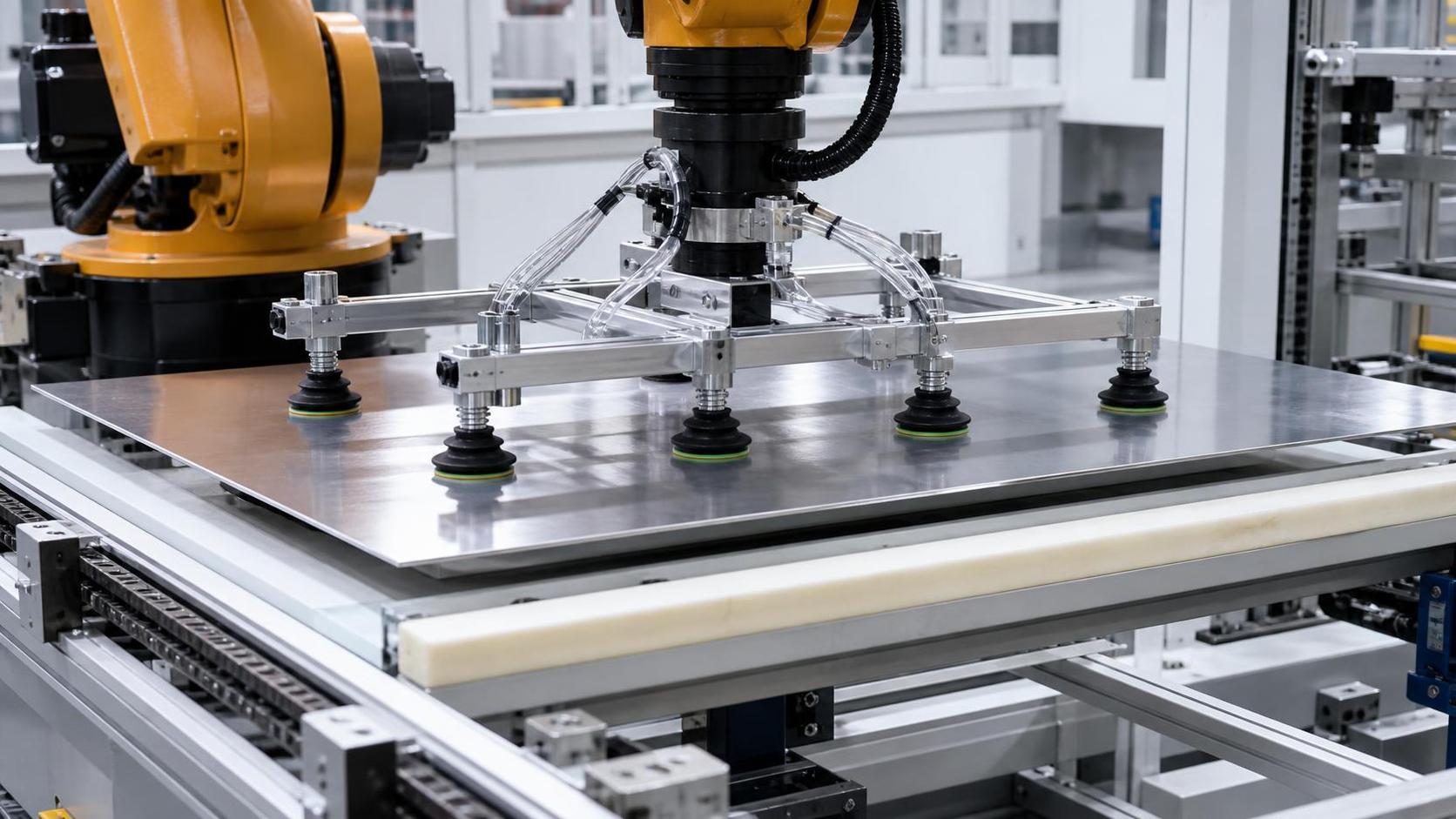
For many flat steel sheets, vacuum gripping is the first option considered because it avoids mechanical clamping on visible surfaces. It can be an excellent solution, but it needs proper engineering. Cup material, cup diameter, vacuum reserve, spacing, and the number of pickup points all affect performance.
A polished stainless sheet and a rough hot-rolled carbon steel plate should not be treated as the same handling task. Rough or scaled surfaces may reduce vacuum sealing reliability. Oily plates may create slip risk. Perforated sheets and laser-cut blanks may not offer enough uninterrupted area for conventional cups. Protective film can also change friction and introduce the possibility of film distortion if the cups are too aggressive.
For sensitive finished surfaces, operators should look for non-marking cup materials and make cup cleaning part of routine maintenance. A soft cup covered with metal dust can mark a sheet just as easily as a hard component. In plants processing several materials, it is often sensible to separate grippers or at least establish a strict cleaning and changeover procedure rather than using one dirty end effector across all product types.
Magnetic grippers can be effective for ferrous plates, particularly where surface conditions make vacuum unreliable. However, they require careful evaluation for thin sheet, residual magnetism concerns, uneven surfaces, and the type of finish being handled. Mechanical clamps are appropriate in some applications, but their contact areas should be positioned on sacrificial edges, trimmed zones, or non-cosmetic areas whenever possible.
The safest grip is not necessarily the strongest grip. It is the grip that holds the plate securely with the least contact pressure and the least opportunity for movement.
Support the sheet so it does not bend into trouble
A plate may remain attached to the robot and still be mishandled. Thin, long, or wide sheets can deflect under their own weight. When this happens, the free edge may strike a machine table, bend downward into a stack, or contact a safety fence during rotation. The result is not always visible immediately; some deformation only becomes apparent when the sheet reaches a press brake, roll former, or welding fixture.
A good handling robot arm for steel plates uses pickup points that distribute the load over the plate area. The gripper frame should be selected for the maximum plate dimensions as well as the thinnest material likely to be processed. This is one of the details sometimes missed during project planning: a cell designed around the heaviest plate may not handle the thinnest plate gracefully.
For mixed production, adjustable cross-members, independently controlled vacuum zones, or configurable gripper layouts can help. If the robot frequently handles parts with cutouts, narrow strips, or irregular profiles, each pickup zone needs verification. A vacuum sensor can confirm that suction exists, but it cannot by itself guarantee that the sheet is balanced. The program must also account for the center of gravity and the risk of a part peeling away during acceleration.
Program smooth motion instead of chasing maximum speed
Surface damage is often a motion-control issue. High acceleration and abrupt stops can make a plate oscillate, particularly after a 90-degree rotation or when a large sheet is held horizontally. A swinging plate can hit tooling, scrape a guide, or land off-center. Reducing cycle time has value, but a few tenths of a second saved in transfer is rarely worth a rejected finished part.
Robot paths should include sufficient clearance above stacks, machine beds, and fixtures. The final approach to a placement point should be slower than the main travel path. Instead of dropping a plate onto hard supports, the robot should lower it in a controlled way, confirm contact, release the grip, and retract vertically before moving away. This sequence prevents lateral dragging at the moment of release.
It is also worth checking orientation logic. If a plate has a protected face, brushed direction, film side, or weld-preparation side, the robot program must preserve the correct presentation at every transfer. A reliable cell should not depend on an operator remembering which face was upward on the incoming stack.
The stack and the workstation need as much attention as the robot
Even a well-designed end effector cannot protect a plate if the receiving station is poorly prepared. Steel-on-steel contact at a stack can create scratches, particularly where sheets are shifted into alignment. Depending on the material and process, separation layers, clean support pads, low-friction strips, or protected locating surfaces may be appropriate. The right choice depends on whether the plate must remain perfectly clean, whether it has protective film, and how quickly it moves to the next operation.
Support points should be level and free of sharp edges. A single worn roller or chipped fixture pad can leave a recurring mark that operators may mistakenly blame on the robot. Regular inspection matters because these problems are usually gradual: dust accumulates, pads harden, guide surfaces wear, and a previously safe placement path becomes marginal.
Separating sheets is another practical challenge. Light oil, static effects, protective film, and slight sheet bow can cause double-sheet pickup. A robot cell may need thickness sensing, vacuum monitoring by zone, sheet-separation devices, or a verification step before transfer. Double sheets create more than a quality concern; they can overload downstream tooling or cause a crash in a closely toleranced machine.
Integrate handling with the fabrication sequence
The best automation decisions are made by looking beyond the loading station. A steel plate entering a laser cutter, press brake, rolling machine, or welding fixture may need different orientation, tolerance, and surface protection. The robot should deliver the part in a way that reduces manual correction downstream. If an operator must push every sheet into position after robotic placement, that manual adjustment can reintroduce the very scratches and dents the system was meant to eliminate.
This becomes particularly relevant in cylindrical and longitudinal-seam production. After plate rolling, a shell must often be presented carefully to a welding station without damaging the formed surface or upsetting seam alignment. Equipment such as a Longitudinal seam welding machine can use closely arranged pneumatic clamping along the seam to apply force evenly and help control thermal deformation. In that type of process, robot handling should place the workpiece accurately enough that the clamps do not need to compensate for careless transfer.
For example, the ZF series is available with welding lengths up to 3000 mm and is intended for workpieces within stated thickness and diameter ranges. That does not mean every plate-handling robot is automatically compatible. The gripper, robot reach, fixture access, loading height, shell diameter, and safety layout all need to be checked together. This is where experienced equipment integration is more useful than selecting machines one by one from separate catalogs.
Give operators useful controls, not just an automatic cycle
Automation does not remove the operator from the quality loop. It changes the operator’s role from physically carrying material to monitoring conditions, responding to exceptions, and maintaining the handling standard. Operators should be able to identify low-vacuum alarms, misaligned sheets, cup contamination, abnormal plate flexing, and changes in stack condition before a fault becomes a damaged batch.
A practical operating procedure should include a pre-shift check of cups or magnets, gripper fasteners, sensor status, protective contact surfaces, and the area beneath the transfer path. When a new plate grade, thickness, finish, or sheet size is introduced, the first few cycles should be observed at reduced speed. This is not wasted production time. It is how a team confirms that the programmed motion still fits the real material.
In many fabrication projects, the difference between a reliable cell and a troublesome one comes down to these small operational details. Wuxi Samgins International Trade Co., Ltd., which supplies fabrication equipment including cutting, forming, welding, deburring, and automated systems, approaches equipment selection with that wider process connection in mind. For facilities working across different sheet-metal operations, compatibility between handling, machine loading, and finishing requirements deserves early discussion rather than a late adjustment on the shop floor.
What to confirm before specifying the robot arm
Before finalizing a system, document the actual plate range: material grades, maximum and minimum dimensions, thicknesses, surface finishes, coatings, protective films, hole patterns, and expected stack condition. Also define where marks are acceptable and where they are not. A carbon steel blank headed for abrasive blasting has different handling priorities from a visible stainless enclosure panel.
Then review the complete transfer route. Ask where the plate could touch anything, whether it can flex, how the system detects a failed or double pickup, and what happens during an emergency stop. Confirm cleaning access for cups, supports, and fixtures. Finally, test the most difficult material—not only the standard plate used for demonstration.
A handling robot arm prevents surface damage when its grip, support, motion, and receiving stations work as one controlled process. The robot provides repeatability, but careful application engineering is what turns that repeatability into clean plates, safer work, and fewer avoidable interruptions at the next machine.
search
Products Navigation
Send Us A Message