




Which gripper suits a handling robot arm for sheet metal?
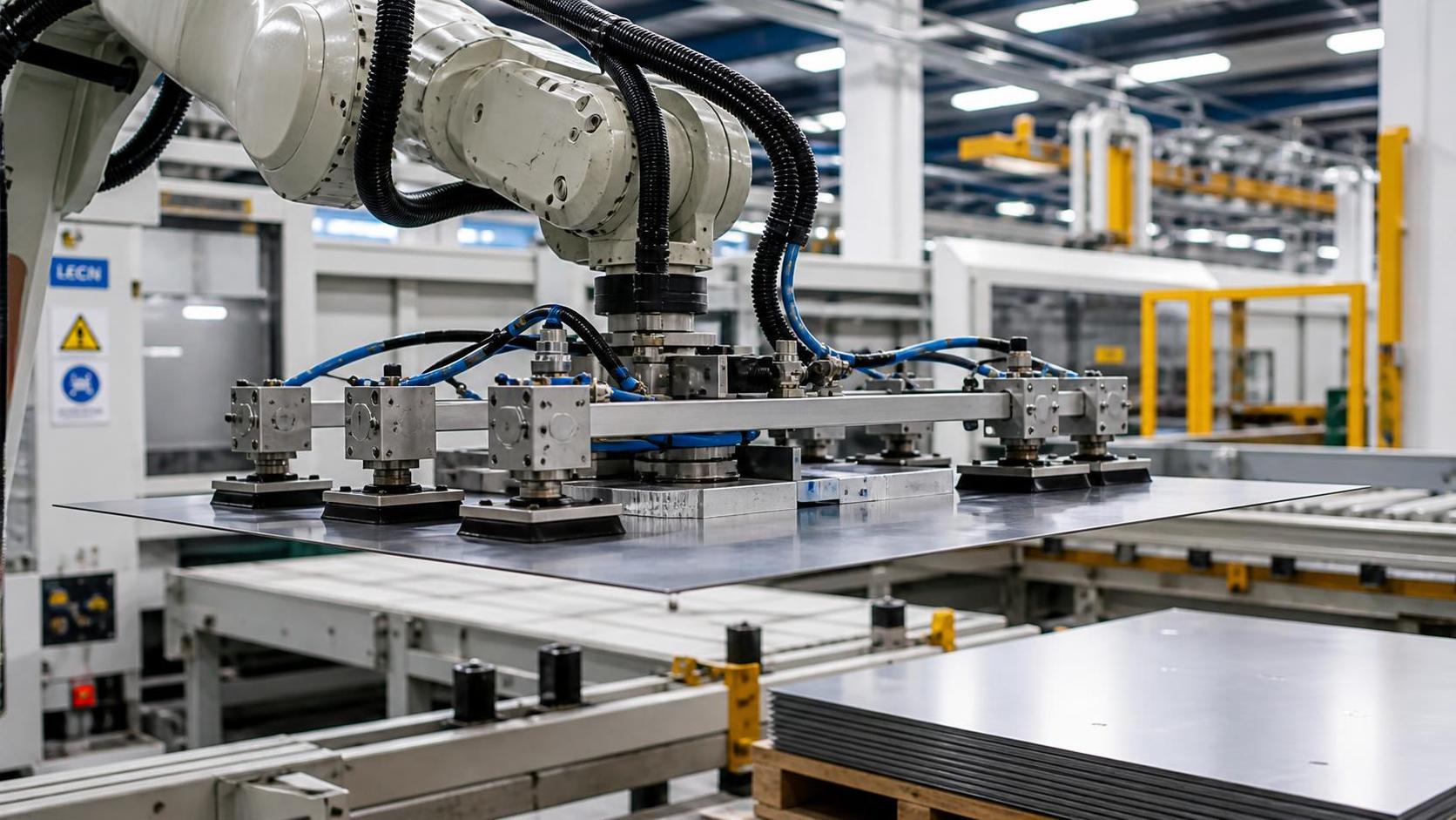
Choosing a gripper for a handling robot arm for sheet metal is rarely a matter of picking the technology with the highest published payload. In real fabrication cells, the gripper has to cope with oily blanks, thin panels that flex under their own weight, sharp edges, protective films, stacked sheets with inconsistent separation, and surfaces that cannot be marked or scratched. A poor match can turn an otherwise capable robot into a source of dropped parts, double picks, damaged finishes, and lost cycle time.
For technical evaluators, the useful question is not simply “vacuum or magnet?” It is: what must the end effector control during pickup, transport, orientation, placement, and release? The answer depends on the sheet material, geometry, process route, surface requirements, and the level of production variation the system must absorb.
Start with the sheet, not the robot
Robot reach and payload are important, but the sheet itself defines most of the gripping challenge. Before comparing gripper suppliers or models, establish a handling profile for the complete range of workpieces.
- Material: mild steel, stainless steel, aluminum, galvanized sheet, coated plate, or non-ferrous alloy.
- Thickness and stiffness: a 0.8 mm sheet behaves very differently from a 6 mm plate, even when both have the same weight.
- Maximum dimensions and center of gravity: large blanks may have a low mass but create substantial bending moment at the robot wrist.
- Surface condition: dry, oily, dusty, perforated, film-covered, painted, hot, or freshly processed.
- Edge condition: sharp sheared edges, burrs, cutouts, holes, tabs, or formed features.
- Pickup source: a neat stack, a slanted rack, a conveyor, a cutting table, a press brake station, or a welding fixture.
- Process expectation: simple transfer, machine tending, bin picking, turning over, accurate fixture loading, or palletizing.
This information should be gathered for the smallest, largest, thinnest, heaviest, and most difficult parts—not merely the representative part. A handling concept that works well on a flat rectangular blank can fail when the robot encounters a narrow strip, a perforated panel, or a sheet that has retained oil after laser cutting.
The main gripper families and where they fit
Vacuum grippers: flexible and widely used
Vacuum is often the first option considered for sheet-metal automation because it can handle ferrous and non-ferrous materials without gripping the edge. A modular vacuum frame with multiple suction cups can cover a broad range of blank sizes, while individually controlled vacuum zones allow the robot to pick smaller parts without changing the entire tool.
For smooth, reasonably airtight sheets, vacuum provides gentle contact and good adaptability. It is particularly practical for aluminum, stainless steel, galvanized material, and mixed-material production where magnetic gripping is not possible. Bellows cups can accommodate small height differences, while flat cups tend to offer better positional stability on even surfaces.
Its limitations deserve equal attention. Vacuum performance drops on heavily perforated sheets, very rough surfaces, deep embossing, porous protective layers, and sheets with excessive curvature. Oil can either improve sealing or cause cup slip, depending on the cup material and the motion profile. Thin sheets may also bow between cups, especially during fast acceleration or vertical lifting.
A vacuum design for a handling robot arm for sheet metal should therefore include vacuum monitoring, a reserve capacity margin, check valves or independently monitored zones, and a controlled response to pressure loss. The system should distinguish between “part not picked,” “double sheet picked,” and “part lost during travel.” These are different failures and require different corrective actions.
Magnetic grippers: strong for ferrous blanks, selective by nature
Magnetic grippers are compelling when handling carbon steel or other ferromagnetic sheets. They can grip through light oil and tolerate small gaps or textured surfaces better than vacuum cups. Electro-permanent magnets are especially attractive in some applications because they consume power primarily during switching rather than while holding. Permanent magnetic and electromagnetic arrangements are also used, depending on the required release behavior and safety architecture.
The principal constraint is obvious: magnets do not solve aluminum or stainless steel handling unless the stainless grade is magnetic. Yet material compatibility is not the only issue. Thin sheets may cling together, creating a double-pick risk. Residual magnetism can complicate release or downstream welding and assembly in certain cases. A magnetic field may also be unsuitable near sensitive components or where metal chips build up on the gripper face.
For stacked steel blanks, magnetic gripping should be paired with sheet separation measures. These may include air knives, mechanical separators, thickness sensing, or a peel motion that breaks contact between the top blank and the sheet below. Simply increasing magnetic force is not a reliable answer; it can make double-sheet pickup more likely.
Mechanical grippers: positive retention for difficult parts
Mechanical grippers use fingers, clamps, hooks, expanding pins, or edge-gripping mechanisms. Their major advantage is positive mechanical retention. They are useful for formed components, parts with holes, pieces that cannot be sealed by vacuum, and applications involving high acceleration, inversion, or precise placement.
In sheet handling, mechanical gripping often works best when a consistent flange, hole pattern, or sacrificial edge is available. For example, an internal expanding pin can locate a part accurately through a process hole, while edge clamps may support a workpiece that is too perforated for vacuum. The trade-off is that mechanical grippers need clearance for finger entry and release. They can also mark soft material, damage painted surfaces, or interfere with nesting layouts if not carefully designed.
Mechanical solutions are frequently more application-specific than vacuum tooling. That is not a disadvantage when the production mix is stable and the part geometry is well controlled. It becomes less attractive when one robot must handle dozens of unrelated blanks with frequent changeovers.
Hybrid grippers: often the practical answer
Many demanding cells benefit from a hybrid approach: vacuum cups for broad support, magnets for ferrous-sheet security, and mechanical stops or fingers to resist lateral movement. A hybrid tool can also combine vacuum with a sheet separator, camera, thickness sensor, or compliance unit.
This approach adds design complexity and tool mass, but it may be justified where product quality, uptime, and safe recovery matter more than achieving the simplest end-of-arm tool. The robot’s remaining payload must be checked after accounting for the gripper body, valves, sensors, cabling, and worst-case workpiece. A gripper that is technically capable of holding the part but leaves little payload reserve can force slower motion and reduce the expected productivity gain.
A quick selection guide
Do not underestimate dynamic loads
A gripper may lift a blank safely in a stationary test and still fail at production speed. When the robot accelerates, decelerates, rotates the wrist, or makes an emergency stop, the part experiences forces beyond its static weight. Large sheets create additional leverage because their center of gravity may sit far from the wrist flange.
Technical evaluation should consider the worst orientation and the fastest intended trajectory. If a thin panel is moved vertically and then rotated, cup placement must prevent the sheet from folding, sliding, or vibrating. In many cases, better support distribution and a smoother robot path achieve more than adding larger cups or stronger magnets.
It is also wise to evaluate the workpiece as a flexible object. A long sheet can oscillate after a sudden move, creating placement error at the next station. The robot may arrive at the programmed position while the far end of the panel is still moving. A gripper with more support points, reduced acceleration, or an intermediate settling strategy may be needed for accurate loading into a press brake, fixture, or welding station.
Surface protection is a production requirement, not a finishing detail
Scratches, cup marks, and edge dents are often discovered after downstream forming, coating, or assembly, when the original handling cause is harder to identify. For decorative stainless steel, pre-painted sheet, aluminum facings, or film-protected panels, gripper contact materials should be tested on actual production samples.
Choose suction cup compounds that are compatible with the material and any oils or coatings present. Keep contact faces clean, since embedded metal dust can become abrasive. For mechanical gripping, spread the contact load where possible and avoid clamping on visible surfaces. If the process permits, grip a trim area that will later be removed.
Surface protection also includes preventing unintended contact during robot travel. The end effector must clear racks, machine doors, clamps, fixtures, and adjacent parts with enough margin to accommodate sheet flexing. Simulation is helpful, but a physical trial with the largest and least stiff workpiece remains essential.
Integration with the wider fabrication line
The gripper should be selected in the context of the entire material flow. A robot feeding a laser cutting machine faces different conditions from one transferring blanks into a bending cell or loading fabricated members into a welding fixture. Dust, spatter, heat, and fixture tolerances can change the preferred end-effector design.
In structural steel production, handling may move beyond flat blanks to webs, flanges, and assembled components. For fabrication lines that combine automated transfer with beam welding, the robot or manipulator must be evaluated alongside the welding system’s positioning requirements, part size range, and cycle rhythm. Equipment such as a T type gantry h beam welding machine is designed for H- and T-shaped steel fabrication, including workpieces with web heights from 200 to 2000 mm and lengths up to 15,000 mm in the stated configuration. In such a line, gripping and conveying choices should protect fit-up accuracy rather than merely move steel from one point to another.
For example, if a handling device presents a web or flange with inconsistent orientation, the welding station may lose time correcting alignment. Conversely, if the welding cell uses automatic centering and seam tracking, the upstream handling system should still deliver parts within the station’s practical adjustment range. This is where end-effector accuracy, sensor feedback, and fixture design become connected decisions.
Questions to ask during an acceptance trial
A credible trial should use the actual material range, including oily sheets, thin parts, perforated blanks, and the largest format expected in production. Ask the supplier or integrator to demonstrate more than a clean pickup from a perfectly aligned stack.
- Can the system identify a missed pickup before the robot begins a full transfer?
- How does it detect and reject double sheets?
- What happens if one vacuum circuit loses pressure or a cup is partially blocked?
- Is the part stable at the planned acceleration and wrist rotation?
- Can operators change cup positions, magnetic zones, or mechanical fingers without excessive downtime?
- How are gripper wear items inspected and replaced?
- Does the tool maintain clearance around fixtures, clamps, and machine guarding?
- What is the safe state after loss of air, power, or communication?
These questions reveal whether the proposed gripper is a laboratory solution or a production-ready tool. The best design is often not the one with the most features; it is the one that handles the full part range predictably and makes abnormal conditions visible early.
Making the final decision
Vacuum gripping is generally the most versatile starting point for mixed sheet-metal work, especially when non-ferrous materials and protected surfaces are involved. Magnetic grippers are highly effective for suitable steel sheets, provided double-pick and release behavior are properly managed. Mechanical gripping earns its place where positive retention, formed geometry, holes, or perforations make contact-based suction unreliable. Hybrid designs are worth considering when a single production cell must cover several difficult conditions.
For a handling robot arm for sheet metal, the right gripper is ultimately the one that controls the part throughout the real process—not just at the instant of pickup. Evaluators who test edge cases, dynamic motion, surface quality, fault response, and line integration will make a safer decision than those who compare only nominal payload and purchase price. In fabrication automation, that difference is usually felt every day on the shop floor.
search
Products Navigation
Send Us A Message