




Steel Plate Handling Robot Arms: How to Size Payload and Protect Surfaces
Steel Plate Handling Robot Arms: How to Size Payload and Protect Surfaces
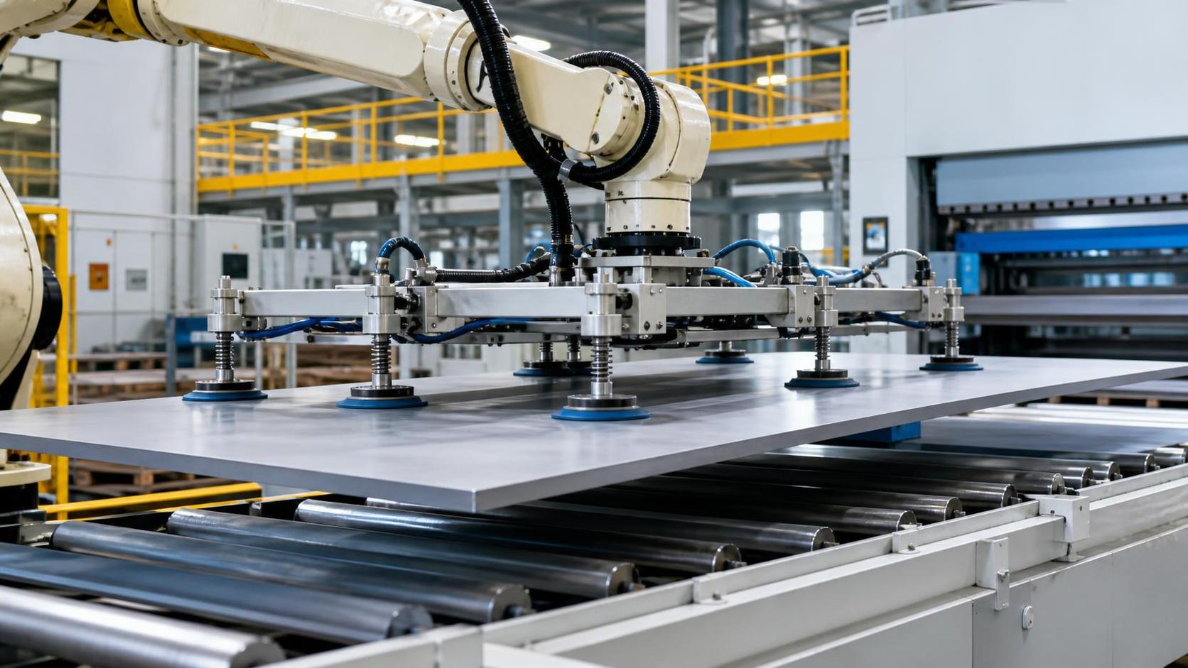
A steel plate handling cell can appear correctly sized on a layout drawing and still fail during commissioning. The usual cause is not the plate’s static weight alone. A robot that can lift a nominal plate may struggle once the end effector, vacuum circuit, lifting frame, acceleration, offset center of gravity, and required safety margin are included. At the same time, a cell that moves plates reliably can still create rejectable scratches, suction marks, edge dents, or slight distortion on thin material.
The practical rule is simple: size a steel plate handling robot arm around the worst credible moving condition, not around the lightest or most frequently handled plate. Calculate the total carried mass and moment at the robot flange, then verify dynamic loading, reach, plate stability, and surface-contact method. Payload rating is necessary, but it is only one of several limiting values.
Start with the real load, not the plate weight
Technical evaluations often begin with a plate mass calculation:
Plate mass = length × width × thickness × material density
That calculation is useful, but it is not the payload requirement. A robot carries the plate together with every moving component below its wrist. Depending on the cell design, this can include a vacuum gripper, magnet modules, beams, hoses, valves, sensors, cable protection, collision brackets, and an adapter plate. The robot controller must manage the combined mass and the location of its center of gravity.
A more useful starting expression is:
Total moving payload = plate mass + end-effector mass + attached utilities and tooling
Then apply a margin that reflects the application rather than choosing an arbitrary percentage. A slow pick-and-place cycle with a compact gripper may need a different allowance from a high-throughput cell that accelerates a large plate through a long horizontal reach. The margin must cover expected plate variation, actual tooling weight, wear items, hose movement, and the difference between a clean dry sheet and production material with oil, mill scale, film, or moisture.
Do not assume that a robot rated for a given payload can use all of that capacity at every orientation. Robot manufacturers typically define payload capability together with allowable wrist moments and inertia limits. A wide but relatively light plate can exceed a moment limit before it reaches the rated mass limit.
Center of gravity is often the first hidden constraint
A compact blank located close to the flange behaves very differently from a long plate supported on a beam. The total center of gravity may sit far below or in front of the wrist, producing substantial torque as the arm accelerates, decelerates, rotates, or changes orientation.
Evaluate center of gravity in all three axes relative to the mounting flange. This requires more than entering the plate dimensions into a quotation form. The end-effector supplier should provide its own mass and center-of-gravity data. For the plate, use the geometric center only when the shape, thickness, and material distribution are uniform. Cut blanks, parts with openings, stacked sheets, and partially supported plates may have a shifted center of gravity.
Three situations deserve particular attention:
- Long rectangular plates: Even a moderate weight can create high wrist torque when the plate is picked near one end or carried in portrait orientation.
- Mixed product programs: A robot sized for a thick, smaller blank may be unsuitable for a thin, wide sheet with a much larger inertia value.
- Off-center pickup locations: Space restrictions, press loading geometry, and fixture interference can force a pick point away from the true center of the sheet.
Ask for robot load verification using the intended end effector and the maximum plate envelope. A supplier should be able to assess mass, center of gravity, moment, and inertia rather than confirming only a payload number. Where a tool will later be modified with extra cups, magnets, cameras, or protective covers, reserve enough capacity for that change instead of treating it as a minor retrofit.
Dynamic force determines whether the cell remains stable
A plate may remain secure while held still yet move or slip during production. Motion creates forces that are absent from a static calculation. Rapid starts and stops can increase loading on cups, magnets, clamps, and robot joints. Rotation is especially demanding because a broad plate has high rotational inertia. A robot can be slowed down to stay within limits, but that may undermine the cycle time used to justify automation.
Define the intended motion before final robot selection: vertical lifting distance, horizontal travel, orientation changes, handoff positions, dwell time, and required parts per hour. The relevant question is not “Can the robot lift it?” but “Can it move this load through this path at the required acceleration without exceeding joint, wrist, gripper, or plate-deflection limits?”
Dynamic conditions become more severe when a plate is handled at maximum reach. In that position, small vibrations and gripper flexibility can cause edge sway. The issue is not merely appearance; sway can disturb machine loading, make location pins difficult to engage, or create collision risk near guarding and fixtures. Reducing acceleration in selected path segments is often more effective than slowing the entire program. For example, the robot may travel quickly while clear of equipment, then use controlled deceleration before placing the plate on a cutting table, press feeder, or inspection station.
Choose the gripping method around surface condition and material behavior
Surface protection begins with identifying what must be protected. “No damage” can mean different things for hot-rolled structural plate, pickled sheet, stainless steel with a cosmetic finish, coated material, aluminum-clad plate, or sheet with temporary protective film. A handling method that is acceptable for a weld preparation stage may be unsuitable before visible-panel fabrication.
Vacuum gripping
Vacuum cups can provide broad, distributed contact and are often suitable where a smooth, relatively airtight surface is available. Their limitations must be evaluated honestly. Oil, scale, rough plate, perforations, warped material, and protective films can reduce holding reliability. Cup lips may also leave temporary marks on sensitive surfaces, particularly when high force, long dwell time, or contaminated cups are involved.
Use cup materials compatible with the plate finish and process environment. Keep contact faces clean, inspect for embedded particles, and avoid dragging a cup across the surface during pickup or placement. A gripper with independently monitored vacuum zones is valuable where plate size varies or occasional openings are present. It can confirm that enough active cups are sealed before motion begins.
Magnetic gripping
Permanent or electrically controlled magnetic systems are effective for ferrous steel, especially where vacuum sealing is unreliable. However, magnetic gripping requires checks for material grade, thickness range, air gap caused by scale or coatings, residual magnetism, and the risk of lifting more than one sheet from a stack. Surface-contact pads still matter; dirt or hard particles between the magnet and plate can scratch the workpiece.
Thin plates require additional scrutiny because the magnetic field can attract adjacent sheets or distort a flexible sheet during lifting. A separator, sheet-thickness detection method, or controlled de-stacking sequence may be needed. Magnets also do not solve every orientation problem; a large sheet can bend or oscillate even when the holding force is sufficient.
Mechanical clamps and edge gripping
Clamps are useful when surface contact must be minimized or when the plate cannot provide reliable vacuum or magnetic engagement. Their trade-off is concentrated load at the edge. Improper jaw geometry can dent edges, damage coatings, or initiate local deformation on thin plate. The clamp area must be compatible with downstream trimming, welding, or bending allowances when possible.
For high-finish material, a guarded gripper design may combine low-mark contact pads, controlled clamping force, and sensors that verify full engagement. This approach can be more complex than vacuum handling, but it can be appropriate where surface quality has greater value than the additional tooling cost.
Plate stiffness changes the robot and gripper decision
Two plates of identical weight do not necessarily need the same handling arrangement. A thin, wide plate may deflect significantly under its own weight. If a gripper supports only the central area, the corners can droop. When the robot changes direction, the sheet can flex and rebound. This increases the likelihood of corner contact, edge damage, unstable placement, and inaccurate transfer into downstream equipment.
For flexible material, increase the number and spacing of support points rather than simply selecting a larger robot. A spreader beam, traversing suction zones, or multiple independently controlled magnetic modules can reduce sag. The goal is to keep the plate stable throughout motion, not merely keep it attached. In some cases, a slower orientation change or a horizontal carry position is necessary to control deflection.
Stack separation is another stiffness-related concern. Thin sheets can adhere through oil, surface tension, burrs, magnetic attraction, or slight nesting. The handling system should detect double sheets before a plate enters a machine. Detection can use thickness measurement, weight verification, magnetic flux monitoring, vacuum behavior, or a combination chosen for the material and process. The detection method should be tested against the actual range of finishes and thicknesses, not only ideal samples.
Use the plate envelope to evaluate reach and interference
Robot reach is frequently misunderstood as the distance from the base to the plate center. In practice, the full plate outline must clear fences, columns, conveyors, machine doors, fixtures, sensors, and other equipment while the wrist follows its programmed path. A large plate can sweep a much wider area than the robot itself.
Build the evaluation around the maximum rectangular envelope, plus any irregular shapes that extend beyond it during pickup or rotation. Check the following positions in simulation or layout review:
- Pickup from the lowest expected stack height and placement at the highest required machine level.
- Approach and retreat paths with the gripper open and with the largest plate attached.
- Wrist rotation near guard openings, machine tables, and nearby tooling.
- Recovery positions after a failed pick or sheet-detection alarm.
- Manual access routes for cup replacement, cleaning, gripper maintenance, and stack replenishment.
Also assess the robot base and pedestal. Raising the robot can improve reach over equipment, but it can increase structural requirements and change the accessible maintenance area. A shorter reach with a well-positioned base is often preferable to running a larger robot near the edge of its working envelope on every cycle.
Surface protection depends on the whole transfer sequence
Marks are not always created at pickup. Plates are commonly damaged when they slide across supports, contact misaligned locating pins, strike stack separators, or settle onto worn rollers. An evaluation focused only on the robot gripper can miss the real source of surface defects.
Map each contact point from incoming stack to downstream process. Identify whether the plate is lifted, rolled, slid, clamped, or temporarily supported at each point. Then review the condition and material of those contacts. Hardened steel supports may be durable but unsuitable for a cosmetic surface without an appropriate cover. Soft pads can protect the surface but may wear, retain debris, or deform enough to affect positioning.
Placement control is equally important. The robot should lower the plate until the support system carries the load, then release only after position and support are confirmed. Releasing too early can cause a drop onto the table. Releasing too late can drag the plate as the robot retracts. A controlled handoff is particularly important before bending, rolling, or forming operations where pre-existing scratches and dents may become more visible after deformation.
In lines producing rolled profiles, flanges, or curved structural components, material transfer should be reviewed together with downstream forming. Equipment such as a Profile bender may operate horizontally or vertically and is intended for precise rolling and calibration work. The robot interface must provide repeatable orientation and adequate support before the workpiece reaches the forming rolls; a handling arm should not be expected to correct distortion created by poor pickup or unstable transfer.
Specify the acceptance criteria before selecting the equipment
Technical approval becomes more reliable when acceptance conditions are written in operational terms. Instead of stating that the robot must “handle plates without damage,” define the material range, maximum dimensions, thickness range, allowable finish condition, stack condition, expected cycle, placement accuracy, and prohibited marks. Include the normal production conditions that affect grip, such as oil level, scale, protective film, holes, cutouts, burrs, and plate temperature where relevant.
A useful specification separates four limits: maximum static mass, maximum dynamic operating load, maximum plate envelope, and maximum allowable surface impact. These limits may point to different design choices. A heavier robot may solve mass and moment concerns, while a longer gripper beam may solve deflection. A different cup compound, lower placement speed, or edge-gripping method may be the answer to surface protection.
Request evidence that the final configuration has been checked with actual tooling data. The robot, end effector, safety device, plate-detection system, and downstream interface should be evaluated as one cell. This prevents a familiar late-stage problem: selecting a robot from a payload chart, then discovering that the real gripper, cables, center of gravity, and required motion leave too little usable capacity.
The strongest selection is rarely the arm with the highest nominal payload. It is the configuration that retains capacity at the required reach, controls the plate through the real cycle, supports flexible sheets adequately, and contacts finished surfaces only in planned, maintainable ways.
search
Recommended Products
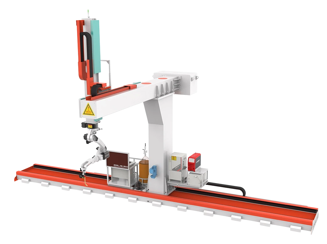
 9 axis cantilever type welding robot9 axis cantilever type welding robot for large steel workpieces with auto tracking, 3D import, and efficient CNC welding automation.
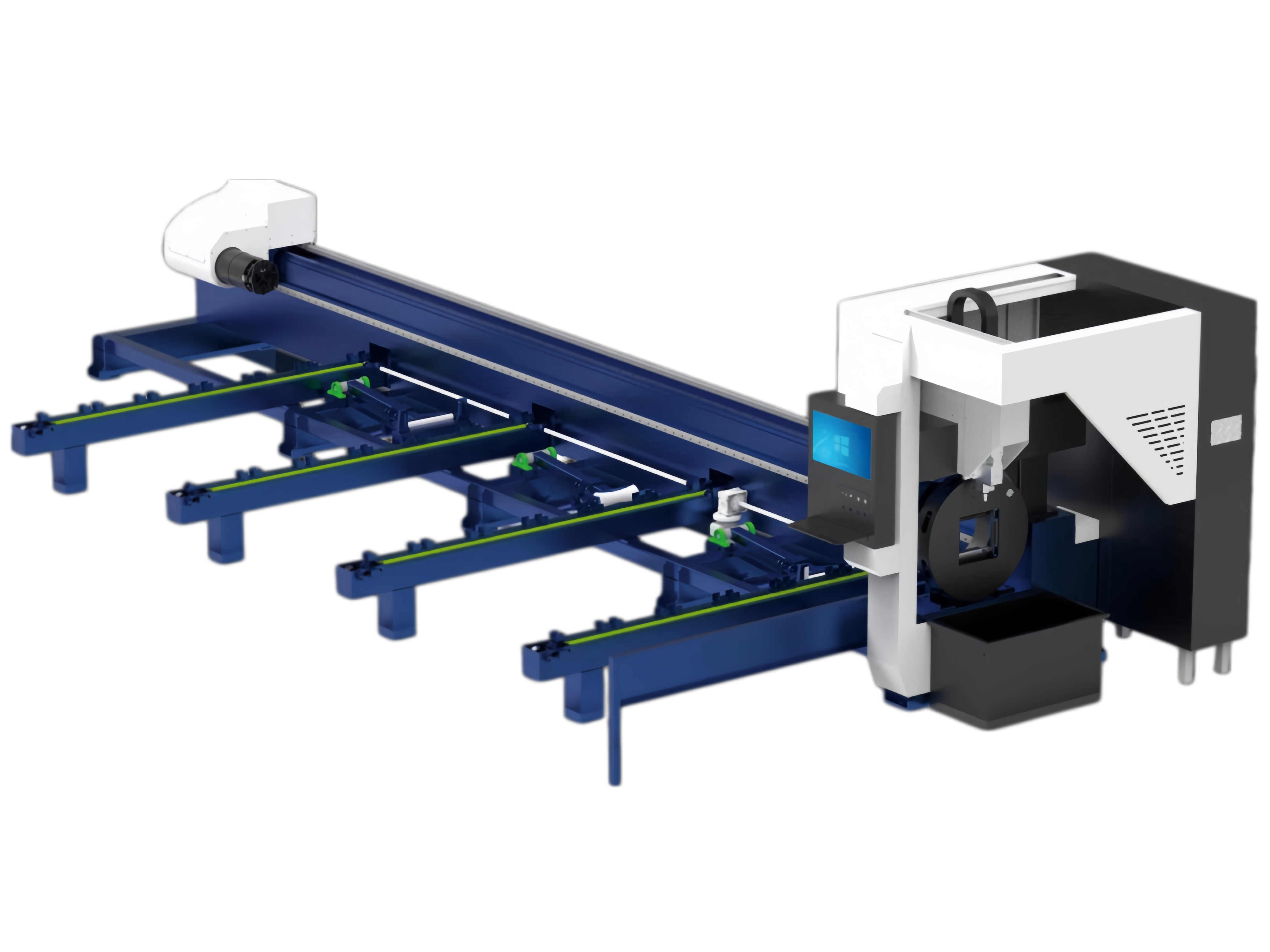
 Pipe cnc fiber laser cutting machine1.Introduction for Pipe cnc fiber laser cutting machine:
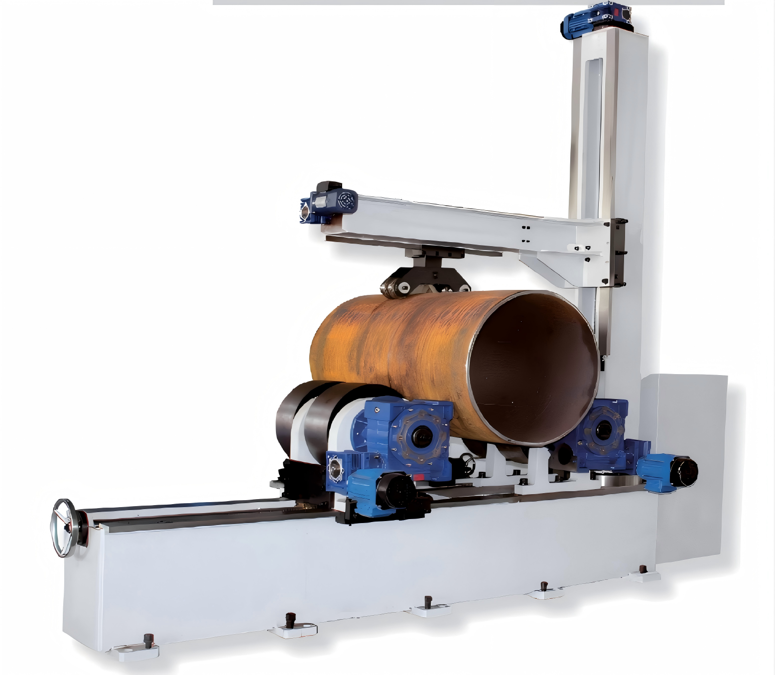
The laser cutting machine focuses the laser beam emitted from the laser source through the optical path system into a high-power-density laser beam. This laser beam is directed onto the surface of the workpiece, causing it to reach the melting point or boiling point. At the same time, the high-pressure gas coaxial with the laser beam blows away the molten or vaporized metal. Beveling & Milling Edge For Heavy TankThis series of heavy tank beveling and milling edge machines is a specialized, high-efficiency solution designed for beveling large storage tanks, pressure vessels, and heavy structural components. The main frame features an integrated welded construction followed by high-temperature stress-relief annealing, effectively eliminating internal stresses to ensure long-term dimensional stability and prevent deformation. The machine combines high-rigidity design with advanced control technology, purpose-built to handle the challenges of extra-thick plates and oversized workpieces.
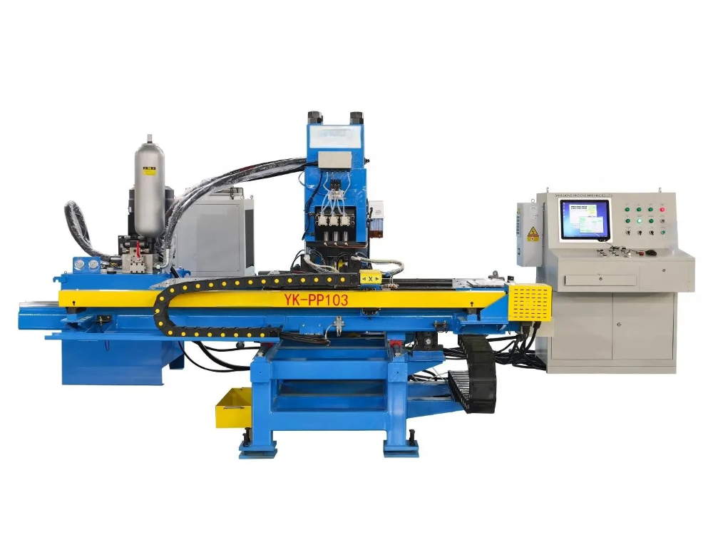
- CNC Punching And Marking Machine For Steel PlatesModels: YK-PP103 / YK-PPR103 / YK-PP104 / YK-PPR104
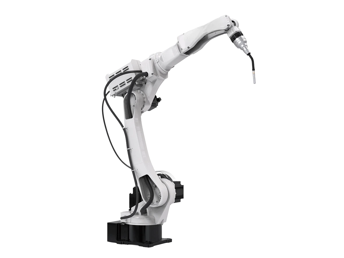
This series is a specialized CNC punching and marking machine designed primarily for steel plate processing in the steel tower industry. It is also well-suited for punching and marking applications across various other industrial sectors. - 6 Axis 2000mm ArmSpan MlG Industrial Welding RobotThis welding robot is designed for reliable arc welding in harsh production environments, featuring a long reach, stable repeatability, and flexible installation.
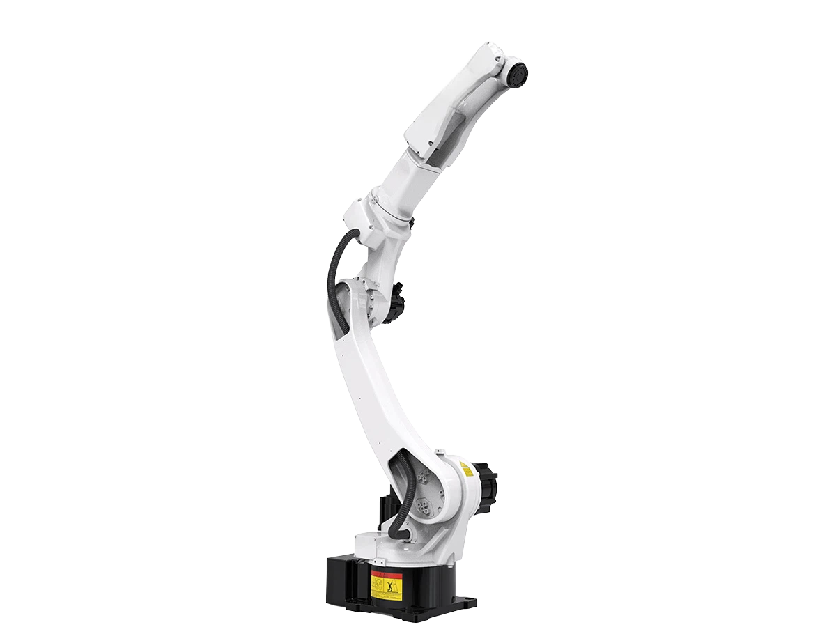
- Multipurpose Handing Robot BR20iB-20Explore the BR20iB-20 multipurpose robot for handling, welding, and cutting with 6-axis motion, ±0.08 mm repeatability, and flexible installation.

Send Us A Message